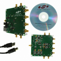
SI5356-EVB Silicon Laboratories Inc, SI5356-EVB Datasheet - Page 10

SI5356-EVB
Manufacturer Part Number
SI5356-EVB
Description
EVALUATION BOARD FOR SI5356
Manufacturer
Silicon Laboratories Inc
Specifications of SI5356-EVB
Main Purpose
Timing, Clock Generator
Utilized Ic / Part
SI5356
Technology Type
Evaluation Board
For Use With/related Products
Si5356
Lead Free Status / RoHS Status
Lead free / RoHS Compliant
Secondary Attributes
-
Embedded
-
Primary Attributes
-
Lead Free Status / Rohs Status
Lead free / RoHS Compliant
Other names
336-1750
Si5356
For synchronous timing applications, the Si5356 can
lock to a 5 to 200 MHz CMOS reference clock. A typical
interface circuit is shown in Figure 2. A series
termination resistor matching the driver’s output
impedance to the impedance of the transmission line is
recommended to reduce reflections.
Control input signals to SSC_DIS and OEB cannot
exceed 1.3 V yet also need to meet the VOH and VOL
specifications outlined in Table 3 on page 5. When
these inputs are driven from CMOS sources, a resistive
attenuator as shown in the Typical Application Circuits
must be used. Suggested standard 1% resistor values
for RSE and RSH, when using a CMOS source, are
given below.
10
Figure 2. Interfacing CMOS Reference Clocks
Figure 1. Connecting an XTAL to the Si5356
CMOS Level
1.8 V
2.5 V
3.3 V
Rs
XTAL
to the Si5356
RSE ohms
f
1000
1960
3090
VCO
Si5356
50
Figure 3. Silicon Labs' MultiSynth Technology
XA
XB
Divider Select
(DIV1, DIV2)
Fractional-N
Divider
RSH ohms
Si5356
1580
1580
1580
CLKIN
Preliminary Rev. 0.3
MultiSynth
Phase Error
Calculator
3.3. Breakthrough MultiSynth Technology
Modern timing architectures require a wide range of
frequencies which are often non-integer related.
Traditional clock architectures address this by using a
combination of single PLL ICs, 4-PLL ICs and discrete
XOs, often at the expense of BOM complexity and
power. The Si5356 use patented MultiSynth technology
to
integrating the frequency synthesis capability of 4
phase-locked loops (PLLs) in a single device, greatly
minimizing size and power requirements versus
traditional solutions. Based on a fractional-N PLL, the
heart of the architecture is a low phase noise, high-
frequency VCO. The VCO supplies a high frequency
output clock to the MultiSynth block on each of the four
independent output paths. Each MultiSynth operates as
a high-speed fractional divider with Silicon Laboratories'
proprietary phase error correction to divide down the
VCO clock to the required output frequency with very
low jitter.
The first stage of the MultiSynth architecture is a
fractional-N divider which switches seamlessly between
the two closest integer divider values to produce the
exact output clock frequency with 0 ppm error. To
eliminate phase error generated by this process,
MultiSynth calculates the relative phase difference
between the clock produced by the fractional-N divider
and the desired output clock and dynamically adjusts
the phase to match the ideal clock waveform. This novel
approach makes it possible to generate any output
clock frequency without sacrificing jitter performance.
Based on this architecture, each clock output can
produce any frequency from 1 to 200 MHz.
dramatically
Adjust
Phase
simplify
f
OUT
timing
architectures
by


