AC164112 Microchip Technology, AC164112 Datasheet - Page 94
AC164112
Manufacturer Part Number
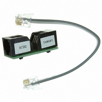
AC164112
Description
VOLTAGE LIMITER MPLAB ICD2 VPP
Manufacturer
Microchip Technology
Datasheet
1.AC164112.pdf
(302 pages)
Specifications of AC164112
Accessory Type
Voltage Limiter
Product
Cable Assemblies
Features
Programming And Debugging The Latest PIC12/PIC16/PIC18 Products
Development Tool Type
Hardware - Eval/Demo Board
Lead Free Status / RoHS Status
Lead free / RoHS Compliant
For Use With/related Products
MPLAB®
Lead Free Status / Rohs Status
Lead free / RoHS Compliant
For Use With
MPLAB ICD 2
Lead Free Status / RoHS Status
Lead free / RoHS Compliant, Lead free / RoHS Compliant
Available stocks
Company
Part Number
Manufacturer
Quantity
Price
Company:

Part Number:
AC164112
Manufacturer:
Microchip Technology
Quantity:
135


PIC16F72X/PIC16LF72X
FIGURE 7-4:
7.6.4
The external Resistor-Capacitor (RC) modes support
the use of an external RC circuit. This allows the
designer maximum flexibility in frequency choice while
keeping costs to a minimum when clock accuracy is not
required. There are two modes: RC and RCIO.
In RC mode, the RC circuit connects to OSC1.
OSC2/CLKOUT outputs the RC oscillator frequency
divided by 4. This signal may be used to provide a clock
for external circuitry, synchronization, calibration, test
or other application requirements. Figure 7-5 shows
the external RC mode connections.
TABLE 7-1:
DS41341E-page 94
CONFIG1
OSCCON
OSCTUNE
Legend:
Note 1:
Note 1: A series resistor (R
Name
C1
C2 Ceramic
2: The value of R
3: An additional parallel feedback resistor (R
(1)
Resonator
ceramic resonators with low drive level.
selected.
may be required for proper ceramic resonator
operation.
x = unknown, u = unchanged, – = unimplemented locations read as ‘0’. Shaded cells are not used by oscillators.
See Configuration Word 1 (Register 8-1) for operation of all bits.
EXTERNAL RC MODES
Bit 7
—
—
—
SUMMARY OF REGISTERS ASSOCIATED WITH CLOCK SOURCES
R
P
R
(3)
S (1)
CERAMIC RESONATOR
OPERATION
(XT OR HS MODE)
F
varies with the Oscillator mode
Bit 6
CP
OSC1/CLKIN
OSC2/CLKOUT
—
—
S
R
) may be required for
F
(2)
MCLRE
IRCF1
TUN5
PIC
Bit 5
®
MCU
To Internal
Logic
Sleep
PWRTE
IRCF0
TUN4
Bit 4
P
)
WDTE
TUN3
Bit 3
ICSL
FOSC2
FIGURE 7-5:
In RCIO mode, the RC circuit is connected to OSC1.
OSC2 becomes an additional general purpose I/O pin.
The RC oscillator frequency is a function of the supply
voltage, the resistor (R
and the operating temperature. Other factors affecting
the oscillator frequency are:
• threshold voltage variation
• component tolerances
• packaging variations in capacitance
The user also needs to take into account variation due
to tolerance of external RC components used.
TUN2
ICSS
Bit 2
R
C
Note 1:
V
Recommended values: 10 kΩ ≤ R
EXT
EXT
SS
V
F
I/O
OSC
DD
(2)
2:
FOSC1
TUN1
Bit 1
/4 or
—
Alternate pin functions are described in
Section 6.1 “Alternate Pin Function”.
Output depends upon RC or RCIO clock mode.
FOSC0
TUN0
Bit 0
OSC1/CLKIN
OSC2/CLKOUT
—
EXT
EXTERNAL RC MODES
© 2009 Microchip Technology Inc.
3 kΩ ≤ R
C
EXT
) and capacitor (C
--10 qq--
--00 0000
POR, BOR
> 20 pF, 2-5V
Value on
PIC
EXT
—
EXT
(1)
®
≤ 100 kΩ, 3-5V
MCU
≤ 100 kΩ, <3V
--10 qq--
--uu uuuu
EXT
Resets
Value on
all other
Internal
Clock
—
) values
(1)
Related parts for AC164112
Image
Part Number
Description
Manufacturer
Datasheet
Request
R

Part Number:
Description:
Manufacturer:
Microchip Technology Inc.
Datasheet:
Part Number:
Description:
Manufacturer:
Microchip Technology Inc.
Datasheet:
Part Number:
Description:
Manufacturer:
Microchip Technology Inc.
Datasheet:
Part Number:
Description:
Manufacturer:
Microchip Technology Inc.
Datasheet:
Part Number:
Description:
Manufacturer:
Microchip Technology Inc.
Datasheet:
Part Number:
Description:
Manufacturer:
Microchip Technology Inc.
Datasheet:
Part Number:
Description:
Manufacturer:
Microchip Technology Inc.
Datasheet:
Part Number:
Description:
Manufacturer:
Microchip Technology Inc.
Datasheet: