AC164112 Microchip Technology, AC164112 Datasheet - Page 111
AC164112
Manufacturer Part Number
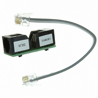
AC164112
Description
VOLTAGE LIMITER MPLAB ICD2 VPP
Manufacturer
Microchip Technology
Datasheet
1.AC164112.pdf
(302 pages)
Specifications of AC164112
Accessory Type
Voltage Limiter
Product
Cable Assemblies
Features
Programming And Debugging The Latest PIC12/PIC16/PIC18 Products
Development Tool Type
Hardware - Eval/Demo Board
Lead Free Status / RoHS Status
Lead free / RoHS Compliant
For Use With/related Products
MPLAB®
Lead Free Status / Rohs Status
Lead free / RoHS Compliant
For Use With
MPLAB ICD 2
Lead Free Status / RoHS Status
Lead free / RoHS Compliant, Lead free / RoHS Compliant
Available stocks
Company
Part Number
Manufacturer
Quantity
Price
Company:

Part Number:
AC164112
Manufacturer:
Microchip Technology
Quantity:
135


11.0
The Timer0 module is an 8-bit timer/counter with the
following features:
• 8-bit timer/counter register (TMR0)
• 8-bit prescaler (shared with Watchdog Timer)
• Programmable internal or external clock source
• Programmable external clock edge selection
• Interrupt on overflow
• TMR0 can be used to gate Timer1
Figure 11-1 is a block diagram of the Timer0 module.
11.1
The Timer0 module can be used as either an 8-bit timer
or an 8-bit counter.
11.1.1
The Timer0 module will increment every instruction
cycle, if used without a prescaler. 8-Bit Timer mode is
selected by clearing the T0CS bit of the OPTION
register.
FIGURE 11-1:
© 2009 Microchip Technology Inc.
WDTE
Cap. Sensing
T1GSS = 11
TMR1GE
Oscillator
T0CKI
F
OSC
TIMER0 MODULE
Timer0 Operation
/4
8-BIT TIMER MODE
T0XCS
0
1
T0SE
BLOCK DIAGRAM OF THE TIMER0/WDT PRESCALER
Low-Power
WDT OSC
T0CS
0
1
Divide by
512
PSA
0
1
Prescaler
PIC16F72X/PIC16LF72X
8-bit
8
PS<2:0>
When TMR0 is written, the increment is inhibited for
two instruction cycles immediately following the write.
11.1.2
In 8-Bit Counter mode, the Timer0 module will
increment on every rising or falling edge of the T0CKI
pin or the Capacitive Sensing Oscillator (CPSOSC)
signal.
8-Bit Counter Mode using the T0CKI pin is selected by
setting the T0CS bit in the OPTION register to ‘1’ and
resetting the T0XCS bit in the CPSCON0 register to ‘0’.
8-Bit Counter Mode using the Capacitive Sensing
Oscillator (CPSOSC) signal is selected by setting the
T0CS bit in the OPTION register to ‘1’ and setting the
T0XCS bit in the CPSCON0 register to ‘1’.
The rising or falling transition of the incrementing edge
for either input source is determined by the T0SE bit in
the OPTION register.
Note:
The value written to the TMR0 register can
be adjusted, in order to account for the two
instruction cycle delay when TMR0 is
written.
8-BIT COUNTER MODE
PSA
PSA
1
0
1
0
Time-out
2 T
Sync
WDT
CY
Set Flag bit T0IF
Overflow to Timer1
DS41341E-page 111
on Overflow
Data Bus
8
TMR0
Related parts for AC164112
Image
Part Number
Description
Manufacturer
Datasheet
Request
R

Part Number:
Description:
Manufacturer:
Microchip Technology Inc.
Datasheet:
Part Number:
Description:
Manufacturer:
Microchip Technology Inc.
Datasheet:
Part Number:
Description:
Manufacturer:
Microchip Technology Inc.
Datasheet:
Part Number:
Description:
Manufacturer:
Microchip Technology Inc.
Datasheet:
Part Number:
Description:
Manufacturer:
Microchip Technology Inc.
Datasheet:
Part Number:
Description:
Manufacturer:
Microchip Technology Inc.
Datasheet:
Part Number:
Description:
Manufacturer:
Microchip Technology Inc.
Datasheet:
Part Number:
Description:
Manufacturer:
Microchip Technology Inc.
Datasheet: