AC164112 Microchip Technology, AC164112 Datasheet - Page 178
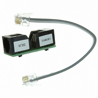
AC164112
Manufacturer Part Number
AC164112
Description
VOLTAGE LIMITER MPLAB ICD2 VPP
Manufacturer
Microchip Technology
Datasheet
1.AC164112.pdf
(302 pages)
Specifications of AC164112
Accessory Type
Voltage Limiter
Product
Cable Assemblies
Features
Programming And Debugging The Latest PIC12/PIC16/PIC18 Products
Development Tool Type
Hardware - Eval/Demo Board
Lead Free Status / RoHS Status
Lead free / RoHS Compliant
For Use With/related Products
MPLAB®
Lead Free Status / Rohs Status
Lead free / RoHS Compliant
For Use With
MPLAB ICD 2
Lead Free Status / RoHS Status
Lead free / RoHS Compliant, Lead free / RoHS Compliant
Available stocks
Company
Part Number
Manufacturer
Quantity
Price
Company:

Part Number:
AC164112
Manufacturer:
Microchip Technology
Quantity:
135


PIC16F72X/PIC16LF72X
17.2.2
During times of no data transfer (Idle time), both the
clock line (SCL) and the data line (SDA) are pulled high
through external pull-up resistors. The Start and Stop
conditions determine the start and stop of data trans-
mission. The Start condition is defined as a high-to-low
transition of the SDA line while SCL is high. The Stop
condition is defined as a low-to-high transition of the
SDA line while SCL is high.
FIGURE 17-9:
17.2.3
After the valid reception of an address or data byte, the
hardware automatically will generate the Acknowledge
(ACK) pulse and load the SSPBUF register with the
received value currently in the SSPSR register. There
are certain conditions that will cause the SSP module
not to generate this ACK pulse. They include any or all
of the following:
• The Buffer Full bit, BF of the SSPSTAT register,
• The SSP Overflow bit, SSPOV of the SSPCON
• The SSP Module is being operated in Firmware
TABLE 17-2:
DS41341E-page 178
Note 1:
was set before the transfer was received.
register, was set before the transfer was received.
Master mode.
Transfer is Received
Status Bits as Data
BF
0
1
1
0
SDA
SCL
Shaded cells show the conditions where the user software did not properly clear the overflow condition.
START AND STOP CONDITIONS
ACKNOWLEDGE
SSPOV
DATA TRANSFER RECEIVED BYTE ACTIONS
0
0
1
1
START AND STOP CONDITIONS
Condition
Start
S
SSPSR → SSPBUF
Data Allowed
Change of
Yes
No
No
No
Figure 17-9 shows the Start and Stop conditions. A
master device generates these conditions for starting
and terminating data transfer. Due to the definition of
the Start and Stop conditions, when data is being trans-
mitted, the SDA line can only change state when the
SCL line is low.
In such a case, the SSPSR register value is not loaded
into the SSPBUF, but bit SSPIF of the PIR1 register is
set. Table 17-2 shows the results of when a data
transfer byte is received, given the status of bits BF and
SSPOV. Flag bit BF is cleared by reading the SSPBUF
register, while bit SSPOV is cleared through software.
Generate ACK
Pulse
Yes
No
No
No
Data Allowed
Change of
© 2009 Microchip Technology Inc.
(SSP Interrupt occurs
Condition
Stop
Set bit SSPIF
P
if enabled)
Yes
Yes
Yes
Yes
Related parts for AC164112
Image
Part Number
Description
Manufacturer
Datasheet
Request
R

Part Number:
Description:
Manufacturer:
Microchip Technology Inc.
Datasheet:
Part Number:
Description:
Manufacturer:
Microchip Technology Inc.
Datasheet:
Part Number:
Description:
Manufacturer:
Microchip Technology Inc.
Datasheet:
Part Number:
Description:
Manufacturer:
Microchip Technology Inc.
Datasheet:
Part Number:
Description:
Manufacturer:
Microchip Technology Inc.
Datasheet:
Part Number:
Description:
Manufacturer:
Microchip Technology Inc.
Datasheet:
Part Number:
Description:
Manufacturer:
Microchip Technology Inc.
Datasheet:
Part Number:
Description:
Manufacturer:
Microchip Technology Inc.
Datasheet: