AC164112 Microchip Technology, AC164112 Datasheet - Page 54
AC164112
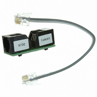
Manufacturer Part Number
AC164112
Description
VOLTAGE LIMITER MPLAB ICD2 VPP
Manufacturer
Microchip Technology
Datasheet
1.AC164112.pdf
(302 pages)
Specifications of AC164112
Accessory Type
Voltage Limiter
Product
Cable Assemblies
Features
Programming And Debugging The Latest PIC12/PIC16/PIC18 Products
Development Tool Type
Hardware - Eval/Demo Board
Lead Free Status / RoHS Status
Lead free / RoHS Compliant
For Use With/related Products
MPLAB®
Lead Free Status / Rohs Status
Lead free / RoHS Compliant
For Use With
MPLAB ICD 2
Lead Free Status / RoHS Status
Lead free / RoHS Compliant, Lead free / RoHS Compliant
Available stocks
Company
Part Number
Manufacturer
Quantity
Price
Company:

Part Number:
AC164112
Manufacturer:
Microchip Technology
Quantity:
135


PIC16F72X/PIC16LF72X
6.2
PORTA is a 8-bit wide, bidirectional port. The
corresponding data direction register is TRISA
(Register 6-3). Setting a TRISA bit (= 1) will make the
corresponding PORTA pin an input (i.e., disable the
output driver). Clearing a TRISA bit (= 0) will make the
corresponding PORTA pin an output (i.e., enables
output driver and puts the contents of the output latch
on the selected pin). Example 6-1 shows how to
initialize PORTA.
Reading the PORTA register (Register 6-2) reads the
status of the pins, whereas writing to it will write to the
PORT latch. All write operations are read-modify-write
operations. Therefore, a write to a port implies that the
port pins are read, this value is modified and then
written to the PORT data latch.
REGISTER 6-2:
REGISTER 6-3:
DS41341E-page 54
bit 7
Legend:
R = Readable bit
-n = Value at POR
bit 7-0
bit 7
Legend:
R = Readable bit
-n = Value at POR
bit 7-0
TRISA7
R/W-x
R/W-1
RA7
PORTA and the TRISA Registers
RA<7:0>: PORTA I/O Pin bit
1 = Port pin is > V
0 = Port pin is < V
TRISA<7:0>: PORTA Tri-State Control bit
1 = PORTA pin configured as an input (tri-stated)
0 = PORTA pin configured as an output
TRISA6
R/W-x
R/W-1
RA6
PORTA: PORTA REGISTER
TRISA: PORTA TRI-STATE REGISTER
W = Writable bit
‘1’ = Bit is set
W = Writable bit
‘1’ = Bit is set
IH
IL
TRISA5
R/W-x
R/W-1
RA5
TRISA4
R/W-x
R/W-1
RA4
U = Unimplemented bit, read as ‘0’
‘0’ = Bit is cleared
U = Unimplemented bit, read as ‘0’
‘0’ = Bit is cleared
TRISA3
R/W-x
R/W-1
The TRISA register (Register 6-3) controls the PORTA
pin output drivers, even when they are being used as
analog inputs. The user should ensure the bits in the
TRISA register are maintained set when using them as
analog inputs. I/O pins configured as analog input
always read ‘0’.
EXAMPLE 6-1:
RA3
BANKSEL PORTA
CLRF
BANKSEL ANSELA
CLRF
BANKSEL TRISA
MOVLW
MOVWF
Note:
PORTA
ANSELA
0Ch
TRISA
The ANSELA register must be initialized to
configure an analog channel as a digital
input. Pins configured as analog inputs will
read ‘0’.
TRISA2
R/W-x
R/W-1
RA2
INITIALIZING PORTA
;
;Init PORTA
;
;digital I/O
;
;Set RA<3:2> as inputs
;and set RA<7:4,1:0>
;as outputs
© 2009 Microchip Technology Inc.
x = Bit is unknown
x = Bit is unknown
TRISA1
R/W-1
R/W-x
RA1
TRISA0
R/W-x
R/W-1
RA0
bit 0
bit 0
Related parts for AC164112
Image
Part Number
Description
Manufacturer
Datasheet
Request
R

Part Number:
Description:
Manufacturer:
Microchip Technology Inc.
Datasheet:
Part Number:
Description:
Manufacturer:
Microchip Technology Inc.
Datasheet:
Part Number:
Description:
Manufacturer:
Microchip Technology Inc.
Datasheet:
Part Number:
Description:
Manufacturer:
Microchip Technology Inc.
Datasheet:
Part Number:
Description:
Manufacturer:
Microchip Technology Inc.
Datasheet:
Part Number:
Description:
Manufacturer:
Microchip Technology Inc.
Datasheet:
Part Number:
Description:
Manufacturer:
Microchip Technology Inc.
Datasheet:
Part Number:
Description:
Manufacturer:
Microchip Technology Inc.
Datasheet: