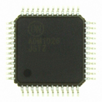
ADM1026JSTZ-REEL ON Semiconductor, ADM1026JSTZ-REEL Datasheet - Page 47

ADM1026JSTZ-REEL
Manufacturer Part Number
ADM1026JSTZ-REEL
Description
IC CNTRL SYS REF/EEPROM 48-LQFP
Manufacturer
ON Semiconductor
Datasheet
1.ADM1026JSTZ-R7.pdf
(55 pages)
Specifications of ADM1026JSTZ-REEL
Function
Hardware Monitor
Topology
ADC, Comparator, Multiplexer, Register Bank
Sensor Type
External & Internal
Sensing Temperature
0°C ~ 100°C, External Sensor
Output Type
SMBus™
Output Alarm
No
Output Fan
Yes
Voltage - Supply
3 V ~ 5.5 V
Operating Temperature
0°C ~ 100°C
Mounting Type
Surface Mount
Package / Case
48-LFQFP
Full Temp Accuracy
+/- 3 C
Digital Output - Bus Interface
Serial (2-Wire)
Maximum Operating Temperature
+ 100 C
Minimum Operating Temperature
0 C
Lead Free Status / RoHS Status
Lead free / RoHS Compliant
Available stocks
Company
Part Number
Manufacturer
Quantity
Price
Company:
Part Number:
ADM1026JSTZ-REEL
Manufacturer:
AD
Quantity:
6 906
Company:
Part Number:
ADM1026JSTZ-REEL
Manufacturer:
ON Semiconductor
Quantity:
10 000
Part Number:
ADM1026JSTZ-REEL
Manufacturer:
ON/安森美
Quantity:
20 000
Part Number:
ADM1026JSTZ-REEL7
Manufacturer:
ADI/亚德诺
Quantity:
20 000
1. GPIO status bits can be written only when a GPIO pin is configured as output. Read−only otherwise.
Table 47. Register 25h, Status Register 6 (Power−On Default, 00h)
Table 48. Register 26h, V
Table 49. Register 27h, A
7–0
7–0
Bit
Bit
Bit
0
1
2
3
4
5
6
7
GPIO10 Status = 0
GPIO12 Status = 0
GPIO13 Status = 0
GPIO14 Status = 0
GPIO15 Status = 0
GPIO11 Status = 0
GPIO8 Status = 0
GPIO9 Status = 0
V
A
BAT
IN8
Name
Name
Name
Value
Value
BAT
IN8
Measured Value (Power−On Default, 00h)
Measured Value (Power−On Default, 00h)
(Note 1)
R/W
R/W
R/W
R/W
R/W
R/W
R/W
R/W
R/W
R/W
R/W
R
R
R
R
R
R
R
R
R
R
When GPIO8 is configured as an input, this bit is set when GPIO8 is asserted.
(Asserted may be active high or active low depending on setting of Bit 1 in GPIO
Configuration Register 3.)
When GPIO8 is configured as an output, setting this bit asserts GPIO8. (Asserted
may be active high or active low depending on setting of Bit 1 in GPIO Configuration
Register 3.)
When GPIO9 is configured as an input, this bit is set when GPIO9 is asserted.
(Asserted may be active high or active low depending on setting of Bit 3 in GPIO
Configuration Register 3.)
When GPIO9 is configured as an output, setting this bit asserts GPIO9. (Asserted
may be active high or active low depending on setting of Bit 3 in GPIO Configuration
Register 3.)
When GPIO10 is configured as an input, this bit is set when GPIO10 is asserted.
(Asserted may be active high or active low depending on setting of Bit 5 in GPIO
Configuration Register 3.)
When GPIO10 is configured as an output, setting this bit asserts GPIO10. (Asserted
may be active high or active low depending on setting of Bit 5 in GPIO Configuration
Register 3.)
When GPIO11 is configured as an input, this bit is set when GPIO11 is asserted.
(Asserted may be active high or active low depending on setting of Bit 7 in GPIO
Configuration Register 3.)
When GPIO11 is configured as an output, setting this bit asserts GPIO11. (Asserted
may be active high or active low depending on setting of Bit 7 in GPIO Configuration
Register 3.)
When GPIO12 is configured as an input, this bit is set when GPIO12 is asserted.
(Asserted may be active high or active low depending on setting of Bit 1 in GPIO
Configuration Register 4.)
When GPIO12 is configured as an output, setting this bit asserts GPIO12. (Asserted
may be active high or active low depending on setting of Bit 1 in GPIO Configuration
Register 4.)
When GPIO13 is configured as an input , this bit is set when GPIO13 is asserted.
(Asserted may be active high or active low depending on setting of Bit 3 in GPIO
Configuration Register 4.)
When GPIO13 is configured as an output, setting this bit asserts GPIO13. (Asserted
may be active high or active low depending on setting of Bit 3 in GPIO Configuration
Register 4.)
When GPIO14 is configured as an input , this bit is set when GPIO14 is asserted.
(Asserted may be active high or active low depending on setting of Bit 5 in GPIO
Configuration Register 4.)
When GPIO14 is configured as an output, setting this bit asserts GPIO14. (Asserted
may be active high or active low depending on setting of Bit 5 in GPIO Configuration
Register 4.)
When GPIO15 is configured as an input, this bit is set when GPIO15 is asserted.
(Asserted may be active high or active low depending on setting of Bit 7 in GPIO
Configuration Register 4.)
When GPIO15 is configured as an output, setting this bit asserts GPIO15. (Asserted
may be active high or active low depending on setting of Bit 7 in GPIO Configuration
Register 4.)
This register contains the measured value of the V
This register contains the measured value of the A
http://onsemi.com
47
Description
Description
Description
BAT
IN8
analog input channel.
analog input channel.


