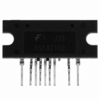
FSFA2100 Fairchild Semiconductor, FSFA2100 Datasheet - Page 12

FSFA2100
Manufacturer Part Number
FSFA2100
Description
IC SWIT OVP UVLO 9SIP
Manufacturer
Fairchild Semiconductor
Datasheet
1.FSFA2100.pdf
(16 pages)
Specifications of FSFA2100
Output Isolation
Isolated
Frequency Range
94 ~ 106kHz
Voltage - Input
14.5 ~ 25 V
Voltage - Output
650V
Power (watts)
200W
Operating Temperature
-40°C ~ 130°C
Package / Case
9-SIP
Output Voltage
25 V
Output Current
8 A
Output Power
450 W
Switching Frequency
300 KHz
Operating Temperature Range
- 40 C to + 130 C
Mounting Style
Through Hole
Duty Cycle (max)
55 %
Lead Free Status / RoHS Status
Lead free / RoHS Compliant
Available stocks
Company
Part Number
Manufacturer
Quantity
Price
© 2008 Fairchild Semiconductor Corporation
FSFA2100 • Rev. 1.0.0
through the R
frequency. The current through the R
proportional to the total impedance of the connected
resistors. The total impedance at startup is lower than
that of the normal operation because R
R
decreases
Eventually C
the operating frequency is determined by R
During the charging time of C
is higher than during normal operation. In asymmetric
half-bridge converters, a switching period contains
powering and commutation periods. The energy cannot
be transferred to the output side during commutation
period. Since the DC link voltage applied to the V
and the leakage inductance of the main transformer are
fixed, the powering period over the switching period is
shorter in high switching frequencies. As C
the switching frequency decreases and the powering
period over the switching period increases as well. It is
helpful to start SMPS softly with the internal soft-start
time together.
5. Startup: Due to the imbalance of the turn-off
resistance between the high- and low-side MOSFETs,
the voltage across the DC blocking capacitor cannot be
predicted at startup. Additionally, the high-side MOSFET
starts with a large duty cycle since the duty cycle of the
low-side MOSFET increases step-by-step during soft-
start time. Therefore, in the case where high voltage is
already charged in the DC blocking capacitor due to the
higher turn-off resistance of the high-side MOSFET
before startup, a large primary current could flow through
the high-side MOSFET during turn-on time after startup.
For the high-side MOSFET, a long duty cycle and high
SET
in parallel, which means the operating frequency
Figure 24. External Soft-Start Circuit
SS
continuously
T
is fully charged to the R
pin, which determines the operating
from
SS
, the operating frequency
higher
T
T
pin is inversely
pin voltage and
SS
SET
SS
to
is added on
is charged,
only.
nominal.
DL
pin
12
applied voltage make an excessive primary current.
When the high-side MOSFET turns off, the primary
current flows back to the DC link capacitor through the
body diode of the low-side MOSFET. It keeps the same
status even after turning on and off the low-side
MOSFET. When the high-side MOSFET turns on again,
a huge current can flow from the DC link capacitor
through the channel of the high-side MOSFET and body
diode of the low-side one due to the reverse recovery. It
may induce unexpected noise into CS pin.
To avoid this issue, the voltage across the DC blocking
capacitor must be low enough. In general, two resistors
with several MHz can be added on the drain-to-source
terminals of each MOSFET to divide the DC link voltage.
6. Burst Operation: To minimize power dissipation in
standby mode, the FSFA2100 enters burst-mode
operation. As the load decreases, the feedback voltage
decreases. As shown in Figure 25, the device
automatically enters burst mode when the feedback
voltage drops below V
stops and the output voltages start to drop at a rate
dependent on standby current load. This causes the
feedback voltage to rise. Once it passes V
switching resumes. The feedback voltage then falls and
the process repeats. Burst-mode operation alternately
enables and disables switching of the MOSFETs,
thereby reducing switching loss in standby mode.
Vo
V
1.3V
V
1.5V
I
V
FB
ds
ds
set
O
Figure 25. Burst-Mode Operation
t
1
Switching
BL
stop
(1.3V). At this point, switching
t
2
t
3
Switching
stop
www.fairchildsemi.com
t
4
BH
(1.5V),
t


