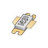
BLL1214-250R NXP Semiconductors, BLL1214-250R Datasheet

BLL1214-250R
Available stocks
Related parts for BLL1214-250R
BLL1214-250R Summary of contents
Page 1
... BLL1214-250R LDMOS L-band radar power transistor Rev. 01 — 4 February 2010 1. Product profile 1.1 General description Silicon N-channel enhancement model LDMOS power transistor encapsulated in a 2-lead flange package (SOT502A) with a ceramic cap. The common source is connected to the flange. Table 1. Typical RF performance at T circuit. ...
Page 2
... T h storage temperature junction temperature Thermal characteristics Parameter transient thermal impedance from junction to heatsink Rev. 01 — 4 February 2010 BLL1214-250R LDMOS L-band radar power transistor Simplified outline Graphic symbol 1 3 [1] 2 Min - − ms; δ ...
Page 3
... D P droop(pulse 6.1 Ruggedness in class-AB operation The BLL1214-250R is capable of withstanding a load mismatch corresponding to VSWR = through all phases under the following conditions 1.2 GHz to 1.4 GHz at rated load power. 7. Application information 7.1 Impedance information Table 8. Typical values unless otherwise specified. f GHz 1 ...
Page 4
... F/m; thickness = 0.64 mm. The other side is unetched and serves multilayer ceramic chip capacitor 39 pF multilayer ceramic chip capacitor 47 pF multilayer ceramic chip capacitor 20 nF multilayer ceramic chip capacitor 36 pF electrolytic capacitor Rev. 01 — 4 February 2010 BLL1214-250R LDMOS L-band radar power transistor drain Z L 001aaf059 Value Remarks ...
Page 5
... Dimensions in mm. The components are situated in one side of the copper-clad Rodgers Duroid 6010 Printed-Circuit Board (PCB); ε = 10.2 F/m; thickness = 0.64 mm. The other side is unetched and serves ground plane. Component layout Rev. 01 — 4 February 2010 BLL1214-250R LDMOS L-band radar power transistor ...
Page 6
... GHz. ( 1.4 GHz. Fig 4. mld860 G (dB) 200 300 P ( 1.2 GHz. ( 1.3 GHz. ( 1.4 GHz. Fig 6. Rev. 01 — 4 February 2010 BLL1214-250R LDMOS L-band radar power transistor P L (3) (2) ( 100 μs; δ Output power as a function of input power; ...
Page 7
... D (%) 50 η 1.35 1.45 f (GHz) Fig 10. Power gain and drain efficiency as function of Rev. 01 — 4 February 2010 BLL1214-250R LDMOS L-band radar power transistor 60 η D (%) (1) ( 100 200 = 100 μs; δ ( 1.2 GHz. ( 1.3 GHz. ...
Page 8
... 19.96 9.50 9.53 1.14 19.94 5.33 19.66 9.30 9.25 0.89 18.92 4.32 0.786 0.374 0.375 0.045 0.785 0.210 0.774 0.366 0.364 0.035 0.745 0.170 REFERENCES JEDEC JEITA Rev. 01 — 4 February 2010 BLL1214-250R LDMOS L-band radar power transistor 3.38 1.70 34.16 9.91 27.94 0.25 3.12 1.45 33.91 9.65 0.133 0.067 1 ...
Page 9
... Laterally Diffused Metal-Oxide Semiconductor Laterally Diffused Metal-Oxide Semiconductor Transistor Radio Frequency Long wave band Voltage Standing-Wave Ratio Data sheet status Product data sheet Rev. 01 — 4 February 2010 BLL1214-250R LDMOS L-band radar power transistor Change notice Supersedes - - © NXP B.V. 2010. All rights reserved ...
Page 10
... In the event that customer uses the product for design-in and use in automotive applications to automotive specifications and standards, customer (a) shall use the product without NXP Semiconductors’ warranty of the Rev. 01 — 4 February 2010 BLL1214-250R LDMOS L-band radar power transistor © NXP B.V. 2010. All rights reserved ...
Page 11
... BLL1214-250R_1 Product data sheet 12.4 Trademarks Notice: All referenced brands, product names, service names and trademarks are the property of their respective owners. http://www.nxp.com salesaddresses@nxp.com Rev. 01 — 4 February 2010 BLL1214-250R LDMOS L-band radar power transistor © NXP B.V. 2010. All rights reserved ...
Page 12
... Please be aware that important notices concerning this document and the product(s) described herein, have been included in section ‘Legal information’. © NXP B.V. 2010. For more information, please visit: http://www.nxp.com For sales office addresses, please send an email to: salesaddresses@nxp.com Document identifier: BLL1214-250R_1 All rights reserved. Date of release: 4 February 2010 ...


