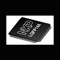
LPC2212_2214 NXP Semiconductors, LPC2212_2214 Datasheet - Page 9

LPC2212_2214
Manufacturer Part Number
LPC2212_2214
Description
The LPC2212/2214 are based on a 16/32-bit ARM7TDMI-S CPU with real-time emulationand embedded trace support, together with 128/256 kB of embedded high-speed flashmemory
Manufacturer
NXP Semiconductors
Datasheet
1.LPC2212_2214.pdf
(47 pages)
NXP Semiconductors
Table 3.
LPC2212_2214
Product data sheet
Symbol
P2[7]/D7
P2[8]/D8
P2[9]/D9
P2[10]/D10
P2[11]/D11
P2[12]/D12
P2[13]/D13
P2[14]/D14
P2[15]/D15
P2[16]/D16
P2[17]/D17
P2[18]/D18
P2[19]/D19
P2[20]/D20
P2[21]/D21
P2[22]/D22
P2[23]/D23
P2[24]/D24
P2[25]/D25
P2[26]/D26/BOOT0
P2[27]/D27/BOOT1
P2[28]/D28
P2[29]/D29
P2[30]/D30/AIN4
P2[31]/D31/AIN5
P3[0] to P3[31]
P3[0]/A0
P3[1]/A1
P3[2]/A2
Pin description
Pin
116
117
118
120
124
125
127
129
130
131
132
133
134
136
137
1
10
11
12
13
16
17
18
19
20
89
88
87
…continued
Type Description
I/O
I/O
I/O
I/O
I/O
I/O
I/O
I/O
I/O
I/O
I/O
I/O
I/O
I/O
I/O
I/O
I/O
I/O
I/O
I/O
I
I/O
I
I/O
I/O
I/O
I
I/O
I
I/O
O
O
O
All information provided in this document is subject to legal disclaimers.
External memory data line 7.
External memory data line 8.
External memory data line 9.
External memory data line 10.
External memory data line 11.
External memory data line 12.
External memory data line 13.
External memory data line 14.
External memory data line 15.
External memory data line 16.
External memory data line 17.
External memory data line 18.
External memory data line 19.
External memory data line 20.
External memory data line 21.
External memory data line 22.
External memory data line 23.
External memory data line 24.
External memory data line 25.
D26 — External memory data line 26.
BOOT0 — While RESET is LOW, together with BOOT1 controls booting and
internal operation. Internal pull-up ensures HIGH state if pin is left
unconnected.
D27 — External memory data line 27.
BOOT1 — While RESET is LOW, together with BOOT0 controls booting and
internal operation. Internal pull-up ensures HIGH state if pin is left
unconnected.
BOOT1:0 = 00 selects 8-bit memory on CS0 for boot.
BOOT1:0 = 01 selects 16-bit memory on CS0 for boot.
BOOT1:0 = 10 selects 32-bit memory on CS0 for boot.
BOOT1:0 = 11 selects internal flash memory.
External memory data line 28.
External memory data line 29.
D30 — External memory data line 30.
AIN4 — ADC, input 4. This analog input is always connected to its pin.
D31 — External memory data line 31.
AIN5 — ADC, input 5. This analog input is always connected to its pin.
Port 3 is a 32-bit bidirectional I/O port with individual direction controls for
each bit. The operation of port 3 pins depends upon the pin function selected
via the Pin Connect Block.
External memory address line 0.
External memory address line 1.
External memory address line 2.
Rev. 5 — 14 June 2011
Single-chip 16/32-bit ARM microcontrollers
LPC2212/2214
© NXP B.V. 2011. All rights reserved.
9 of 47


