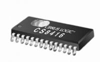
CS8416-CNZ Cirrus Logic Inc, CS8416-CNZ Datasheet - Page 37

CS8416-CNZ
Manufacturer Part Number
CS8416-CNZ
Description
IC RCVR DGTL 192KHZ 28QFN COMM
Manufacturer
Cirrus Logic Inc
Type
Digital Audio Interface Receiverr
Datasheet
1.CS8416-CZZ.pdf
(60 pages)
Specifications of CS8416-CNZ
Applications
Digital Audio
Mounting Type
Surface Mount
Package / Case
28-QFN
Audio Control Type
Digital
Control Interface
I2C, SPI
Control / Process Application
AV & DVD Receivers, CD-R, Digital Mixing Consoles
Supply Voltage Range
3.13V To 5.25V, 3.13V To 3.46V
Lead Free Status / RoHS Status
Lead free / RoHS Compliant
For Use With
598-1017 - BOARD EVAL FOR CS8416 RCVR
Lead Free Status / RoHS Status
Lead free / RoHS Compliant, Lead free / RoHS Compliant
Other names
598-1723
CS8416
1 – Higher Update Rate Phase Detector - Recovered master clock (RMCK) will have low in-band jitter, but
increased wide-band jitter. Use this setting for the best performance when the output is connected to a delta-
sigma digital-to-analog converter (DAC).
TRUNC – Determines if the audio word length is set according to the incoming channel status data as de-
coded by the AUX[3:0] bits. The resulting word length in bits is 24 minus AUX[3:0].
Default = ‘0’
0 – Incoming data is not truncated.
1 – Incoming data is truncated according to the length specified in the channel status data.
Truncation occurs before the de-emphasis filter. TRUNC has no effect on output data if de-emphasis filter
is not used.
Reserved – These bits may change state depending on the input audio data.
14.3
Control1 (01h)
7
6
5
4
3
2
1
0
SWCLK
MUTESAO
INT1
INT0
HOLD1
HOLD0
RMCKF
CHS
SWCLK - Lets OMCK determine RMCK, OSCLK, OLRCK when PLL loses lock
Default = ‘0’
0 - Disable automatic clock switching. RMCK runs at the VCO frequency (~750 kHz) on PLL Unlock.
1 - Enable automatic clock switching on PLL unlock. OMCK clock input is automatically output on RMCK on
PLL Unlock.
MUTESAO - Mute control for the serial audio output port
Default = ‘0’
0 - SDOUT not muted.
1 – SDOUT muted (set to all zeros).
INT[1:0] - Interrupt output pin (INT) control
Default = ‘00’
00 - Active high; high output indicates interrupt condition has occurred.
01 - Active low, low output indicates an interrupt condition has occurred.
10 - Open drain, active low. Requires an external pull-up resistor on the INT pin. Thus it is not recommended
to multiplex INT onto GPO2 in I²C Control Port Mode since an external resistor is required on GPO2 to spec-
ify the AD2 bit of the chip address.
11 – Reserved.
HOLD[1:0] – Determine how received audio sample is affected when a receive error occurs
Default = ‘00’
00 – hold last audio sample.
01 – replace the current audio sample with all zeros (mute).
10- do not change the received audio sample.
11 - reserved
DS578F3
37


