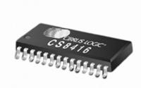
CS8416-CNZ Cirrus Logic Inc, CS8416-CNZ Datasheet - Page 23

CS8416-CNZ
Manufacturer Part Number
CS8416-CNZ
Description
IC RCVR DGTL 192KHZ 28QFN COMM
Manufacturer
Cirrus Logic Inc
Type
Digital Audio Interface Receiverr
Datasheet
1.CS8416-CZZ.pdf
(60 pages)
Specifications of CS8416-CNZ
Applications
Digital Audio
Mounting Type
Surface Mount
Package / Case
28-QFN
Audio Control Type
Digital
Control Interface
I2C, SPI
Control / Process Application
AV & DVD Receivers, CD-R, Digital Mixing Consoles
Supply Voltage Range
3.13V To 5.25V, 3.13V To 3.46V
Lead Free Status / RoHS Status
Lead free / RoHS Compliant
For Use With
598-1017 - BOARD EVAL FOR CS8416 RCVR
Lead Free Status / RoHS Status
Lead free / RoHS Compliant, Lead free / RoHS Compliant
Other names
598-1723
DS578F3
6. GENERAL DESCRIPTION
The CS8416 is a monolithic CMOS device that receives and decodes audio data according to the AES3, IEC60958,
S/PDIF, and EIAJ CP1201 interface standards.
The CS8416 provides an 8:2 multiplexer to select between eight inputs for decoding and to allow an input signal to
be routed to an output of the CS8416. Input data can be either differential or single-ended. A low jitter clock is re-
covered from the incoming data using a PLL. The decoded audio data is output through a configurable, 3-wire serial
audio output port. The channel status and Q-channel subcode portion of the user data are assembled in registers
and may be accessed through an SPI or I²C port.
Three General Purpose Output (GPO) pins are provided to allow a variety of signals to be accessed under software
control. In Hardware Mode, dedicated pins are used to select audio stream inputs for decoding and transmission to
a dedicated TX pin. Hardware Mode also provides channel status and user data output pins.
Figures 5
and Hardware Mode. Please note that all I/O pins, including RXN and RXP[7:0], operate at the VL voltage.
6.1
7. SERIAL AUDIO OUTPUT PORT
A 3-wire serial audio output port is provided. The port can be adjusted to suit the attached device by setting the con-
trol registers. The following parameters are adjustable: master or slave, serial clock frequency, audio data resolu-
tion, left- or right-justification of the data relative to left/right clock, optional one-bit cell delay of the first data bit, the
polarity of the bit clock, and the polarity of the left/right clock. By setting the appropriate control bits, many formats
are possible.
Figure 7
put format is included, which allows the serial output port access to the V, U, and C bits embedded in the serial audio
data stream. When using the part in AES3 direct-output format, the de-emphasis filter must be off (see
on page
of each block. The received channel status block start signal is also available as the RCBL pin in Hardware Mode
and through a GPO pin in Software Mode.
In master mode, the left/right clock (OLRCK) and the serial bit clock (OSCLK) are outputs, derived from the recov-
ered RMCK clock. In slave mode, OLRCK and OSCLK are inputs. OLRCK is normally synchronous to the appropri-
ate master clock, but OSCLK can be asynchronous and discontinuous if required. By appropriate phasing of OLRCK
and control of the serial clocks, multiple CS8416’s can share one serial port. OLRCK should be continuous, but the
duty cycle can be less than the specified typical value of 50% if enough serial clocks are present in each phase to
AES3 and S/PDIF Standards Documents
This document assumes that the user is familiar with the AES3 and S/PDIF data formats. It is advisable to
have current copies of the AES3, IEC60958, and IEC61937 specifications on hand for easy reference.
The latest AES3 standard is available from the Audio Engineering Society or ANSI at
www.ansi.org. Obtain a copy of the latest IEC60958/61937 standard from ANSI or from the International
Electrotechnical Commission at www.iec.ch. The latest EIAJ CP-1201 standard is available from the
Japanese Electronics Bureau.
Application Note 22: Overview of Digital Audio Interface Data Structures contains a useful tutorial on digital
audio specifications, but it should not be considered a substitute for the standards.
The paper An Understanding and Implementation of the SCMS Serial Copy Management System for
Digital Audio Transmission , by Clifton Sanchez, is an excellent tutorial on SCMS. It is available from the
AES as reprint 3518.
38). The P bit, which would normally be a parity bit, is replaced by a Z bit, which is used to indicate the start
shows a selection of common output formats, along with the control bit settings. A special AES3 direct out-
and
6
show the power supply and external connections to the CS8416 when configured for Software Mode
www.aes.org
Section 14.4
CS8416
or at
23


