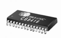
CS8416-CNZ Cirrus Logic Inc, CS8416-CNZ Datasheet - Page 32

CS8416-CNZ
Manufacturer Part Number
CS8416-CNZ
Description
IC RCVR DGTL 192KHZ 28QFN COMM
Manufacturer
Cirrus Logic Inc
Type
Digital Audio Interface Receiverr
Datasheet
1.CS8416-CZZ.pdf
(60 pages)
Specifications of CS8416-CNZ
Applications
Digital Audio
Mounting Type
Surface Mount
Package / Case
28-QFN
Audio Control Type
Digital
Control Interface
I2C, SPI
Control / Process Application
AV & DVD Receivers, CD-R, Digital Mixing Consoles
Supply Voltage Range
3.13V To 5.25V, 3.13V To 3.46V
Lead Free Status / RoHS Status
Lead free / RoHS Compliant
For Use With
598-1017 - BOARD EVAL FOR CS8416 RCVR
Lead Free Status / RoHS Status
Lead free / RoHS Compliant, Lead free / RoHS Compliant
Other names
598-1723
32
11.CHANNEL STATUS AND USER-DATA HANDLING
“Channel Status Buffer Management” on page 51
11.1
11.2
Software Mode
In Software Mode, several options are available for accessing the Channel Status and User data that is en-
coded in the received AES3/SPDIF stream.
The first option allows access directly through registers. The first 5 bytes of the Channel Status block are
decoded into the Receiver Channel Status Registers 19h - 22h. Registers 19h - 1Dh contain the A channel
status data. Registers 1Eh - 22h contain the B channel status data.
Received Channel Status (C), User (U), and EMPH bits may also be output to the GPO pins by appropriately
setting the GPOxSEL bits in control port registers 02h and 03h. In serial port master mode, OLRCK and
RCBL can be made available to qualify the U data output. In serial port slave mode, VLRCK and RCBL can
be made available to qualify the U data output. VLRCK is a virtual word clock, equal to the receiver recov-
ered sample rate, that can be used to frame the C/U output. VLRCK and RCBL are available through the
GPO pins.
The user may also access all of the C and U bits directly from the output data stream (SDOUT) by setting
bits SORES[1:0]=11 (AES3 Direct Mode) in the Serial Audio Data Format register (05h). The appropriate
bits can be stripped from the SDOUT signal by external control logic such as a DSP or microcontroller.
If the incoming User data bits have been encoded as Q-channel subcode, the data is decoded, buffered,
and presented in 10 consecutive register locations (0Eh-17h). An interrupt may be enabled to indicate the
decoding of a new Q-channel block, which may be read through the control port.
The encoded Channel Status bits which indicate sample word length are decoded according to AES3-1992
or IEC 60958. The number of auxiliary bits are reported in bits 7 to 4 of the Receiver Channel Status register
(0Ah).
Hardware Mode
In Hardware Mode, Received Channel Status (C), and User (U) bits are output on pins 19 and 18. In serial
port master mode, OLRCK and RCBL are made available to qualify the C and U data output.
lustrates timing of the C and U data and their related signals.
The user may also access all of the C and U bits directly from the output data stream (SDOUT) by pulling
the AUDIO and C pins high through 47 k Ω resistors to VL (AES3 Direct Mode). The appropriate bits can be
stripped from the SDOUT signal by external control logic such as a DSP or microcontroller. Only OLRCK in
master mode is available to qualify the U output. See
“Hardware Mode Equivalent Register Settings” on page 47
–
–
–
VLRCK
RCBL
(out)
C/U
(out)
(out)
RCBL goes high 2 frames after receipt of a Z preamble and is high for 16 frames.
VLRCK is a virtual work clock, available through the GPO pins, that can be used
to frame the C/U output.
VLRCK duty cycle is 50%. VLRCK frequency is always equal to the incoming
Figure 10
illustrates timing of the C and U data and their related signals.
Figure 10. C/U Data Outputs
describes Channel Status and User data control.
“Hardware Mode Function Selection” on page 46
to configure these pins..
Figure 10
CS8416
DS578F3
and
il-


