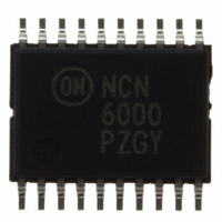
NCN6000DTBR2 ON Semiconductor, NCN6000DTBR2 Datasheet - Page 5

NCN6000DTBR2
Manufacturer Part Number
NCN6000DTBR2
Description
IC INTERFACE SMART CARD 20TSSOP
Manufacturer
ON Semiconductor
Datasheet
1.NCN6000DTBR2.pdf
(36 pages)
Specifications of NCN6000DTBR2
Applications
ATM Terminals, Gas Pumps, ISM
Interface
Microcontroller
Voltage - Supply
2.7 V ~ 6 V
Package / Case
20-TSSOP
Mounting Type
Surface Mount
Lead Free Status / RoHS Status
Contains lead / RoHS non-compliant
Other names
NCN6000DTBR2OSTR
Available stocks
Company
Part Number
Manufacturer
Quantity
Price
Part Number:
NCN6000DTBR2
Manufacturer:
ON/安森美
Quantity:
20 000
Part Number:
NCN6000DTBR2G
Manufacturer:
ON/安森美
Quantity:
20 000
ON or OFF. The identification of the interrupt is carried out
by polling the STATUS pin, the Vbat voltage and the
DC−DC results being provided on the same pin as depicted
pin signal is debounced internally prior to pull the INT pin
to Low. The built−in logic circuit automatically
accommodates positive or negative input signal slope, on
both insertion and extraction state, depending upon the
polarity defined during the initialization sequence. The
default condition is Normally Open switch, negative going
card detection. The external CPU shall acknowledge the
request by forcing CS = L which, in turn, releases the INT
pin to High upon positive going of Chip Select (Table 4).
Polling the STATUS pin as depicted in Table 3 identifies the
active card. If a card is present, the STATUS returns High,
The programming can be achieved with the card powered
When a card is either inserted or extracted, the CRD_DET
S1 CLEAR INTERRUPT
S2 CARD PRESENT: STATUS = 1
S3 CLEAR INTERRUPT
S4 CARD PRESENT: STATUS = 0
CRD_DET
STATUS
PGM
INT
CS
A0
A1
ACKNOWLEDGE
INTERRUPT
50 ms
Figure 5. Interrupt Servicing and Card Polling
http://onsemi.com
CARD IDENTIFICATION
NCN6000
POLLING
5
by the table in Figure 4. During the programming mode, the
PGM pin can be released to High since the mode is internally
latched by the Negative going transition presents on the Chip
Select pin.
otherwise a Low is presented pin 5. The 50 ms digital filter
is activated during both Insertion and Extraction of the card.
The MPU shall clear the INT line when the card has been
extracted, making the interrupt function available for other
purposes. However, neither the NCN6000 operation nor the
smart card I/O line or commands are affected by the state of
the INT pin.
STATUS register can be performed by a single read by the
MPU: states S1 and S2 can be combined in a single
instruction, the same for S3 and S4.
On the other hand, clearing the INT and reading the
CARD EXTRACTED
50 ms
High
Low
Low


