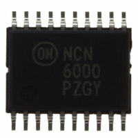
NCN6000DTBR2 ON Semiconductor, NCN6000DTBR2 Datasheet - Page 16

NCN6000DTBR2
Manufacturer Part Number
NCN6000DTBR2
Description
IC INTERFACE SMART CARD 20TSSOP
Manufacturer
ON Semiconductor
Datasheet
1.NCN6000DTBR2.pdf
(36 pages)
Specifications of NCN6000DTBR2
Applications
ATM Terminals, Gas Pumps, ISM
Interface
Microcontroller
Voltage - Supply
2.7 V ~ 6 V
Package / Case
20-TSSOP
Mounting Type
Surface Mount
Lead Free Status / RoHS Status
Contains lead / RoHS non-compliant
Other names
NCN6000DTBR2OSTR
Available stocks
Company
Part Number
Manufacturer
Quantity
Price
Part Number:
NCN6000DTBR2
Manufacturer:
ON/安森美
Quantity:
20 000
Part Number:
NCN6000DTBR2G
Manufacturer:
ON/安森美
Quantity:
20 000
Programming Mode
card power supply, card clock and Card Detection input
logic polarity. These signals (CRD_VCC, CRD_CLK and
CRD_DET) are described in the pin description paragraph
associated with Tables 1 and 3 and Figures 4 and 8.
Active Mode
external MPU and the STATUS pin can be polled to get the
status of either the DC−DC converter or the presence of the
card (inserted or not valid). The power is not connected to
the card: CRD_VCC = 0 V.
Programming Mode
Logic Conditions:
CS
PWR_ON = L
A0
A1
PGM
I/O
RESET
Active Mode
Logic Conditions:
CS
PWR_ON = L
A0
A1
PGM
I/O
RESET
STATUS
The programming mode allows the configuration of the
In the active mode, the NCN6000 is selected by the
= L
= H/L
= H/L
= L
= L/H
= L/H
= L
= L
= L
= H
= Z
= Z
= L/H is Card
Inserted?
Card Output:
CRD_VCC = 0 V
CRD_CLK = L
CRD_RST = L
CRD_IO
Card Output:
CRD_VCC = 0 V
CRD_CLK = L
CRD_RST = L
CRD_IO
RESET
PGM
CS
I/O
A0
A1
= H/L depending upon
the previous I/O pin
logic state
= H/L depending upon
Figure 8. Minimum Programming Timings
the previous I/O pin
logic state
2 ms
PROGRAMMING
http://onsemi.com
1 ms
NCN6000
2 ms
16
card and become logic inputs to control the NCN6000
programming sequence. The programmed values are
latched upon transition of CS from Low to High, PGM being
Low during the transition.
negative going transient, the mode is latched and PGM can
be released to High. This latch is automatically reset when
CS returns to High.
bit a time (using either a STAA or a BSET function), the key
point being the minimum delay between the shorter bit and
the Chip Select pulse. The programmed value is latched into
the NCN6000 register on the CS positive going edge.
previously asserted INT signal upon the positive going
transition.
converter by asserting PWR_ON = H. The NCN6000 will
automatically run a power up sequence when the
CRD_VCC reaches the undervoltage level (either V
V
programmed). The CRD_IO, CRD_RST and CRD_CLK
pins are validated, according to the ISO7816−3 sequence.
The interface is now in transaction mode and the system is
ready for data exchange through the I/O and RESET lines.
At any time, the microcontroller can change the CRD_CLK
frequency and mode, or the CRD_VCC value as determined
by the card being in use.
C3H
The I/O and RESET pins are not connected to the smart
When a programming mode is validated by a Chip Select
The logic input signals can be set simultaneously, or one
The Chip Select pulse [CS] will automatically clear the
If a card is present, the MPU shall activate the DC−DC
, depending upon the CRD_VCC voltage supply
NORMAL MODE
C5H
or


