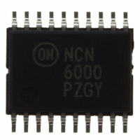
NCN6000DTBR2 ON Semiconductor, NCN6000DTBR2 Datasheet - Page 13

NCN6000DTBR2
Manufacturer Part Number
NCN6000DTBR2
Description
IC INTERFACE SMART CARD 20TSSOP
Manufacturer
ON Semiconductor
Datasheet
1.NCN6000DTBR2.pdf
(36 pages)
Specifications of NCN6000DTBR2
Applications
ATM Terminals, Gas Pumps, ISM
Interface
Microcontroller
Voltage - Supply
2.7 V ~ 6 V
Package / Case
20-TSSOP
Mounting Type
Surface Mount
Lead Free Status / RoHS Status
Contains lead / RoHS non-compliant
Other names
NCN6000DTBR2OSTR
Available stocks
Company
Part Number
Manufacturer
Quantity
Price
Part Number:
NCN6000DTBR2
Manufacturer:
ON/安森美
Quantity:
20 000
Part Number:
NCN6000DTBR2G
Manufacturer:
ON/安森美
Quantity:
20 000
Table 3. Card VCC, Card Clock and Card Detection Polarity Truth Table
Card VCC, Card CLOCK and Card Detection
Polarity Programming
allows matching the system frequency with the card clock
frequency, and to select 3.0 V or 5.0 V CRD_VCC supply.
The CRD_DET programming option allows the usage of
either Normally Open or Normally Close detection switch.
Table 3 highlights the A0, A1, PGM and I/O logic states for
the possible options. The default power up reset condition
HEXA
9. The programmed conditions are latched upon the Chip Select (CS, pin 6) positive going transient.
10. Card clock integrity is guaranteed no spikes whatever be the frequency switching.
11. The STATUS register is not affected when the NCN6000 operates in any of the programming functions.
12. The CRD_VCC and CRD_CLK are not affected when the NCN6000 operates outside their respective decoded logic address.
13. The High Level on STATUS in registers $00 to $0F, inclusive, having being implemented to reduce current consumption but have no other
14. At turn on, the NCN6000 is initialized with CRD_VCC = 3.0V, CLOCK_IN Ratio = 1/1, CRD_CLK = START, CRD_DET = Normally Open.
$0C
$0D
$00
$01
$02
$03
$04
$05
$06
$07
$08
$09
$0A
$0B
$0E
$0F
$10
$12
$14
$16
The CRD_VCC and CLOCK_IN programming options
meanings.
CS
L
L
L
L
L
L
L
L
L
L
L
L
L
L
L
L
L
L
L
L
PWR_ON
−
−
−
−
−
−
−
−
−
−
−
−
−
−
−
−
−
1
−
1
PGM
H
H
H
H
L
L
L
L
L
L
L
L
L
L
L
L
L
L
L
L
RESET
H
H
H
H
H
H
H
H
L
L
L
L
L
L
L
L
Z
Z
Z
Z
A1
H
H
H
H
H
H
H
H
H
H
L
L
L
L
L
L
L
L
L
L
A0
L
H
H
H
H
H
H
H
H
H
H
L
L
L
L
L
L
L
L
L
http://onsemi.com
I/O
L
H
H
H
H
H
H
H
H
Z
Z
Z
Z
L
L
L
L
L
L
L
NCN6000
CRD_VCC
13
3.0 V
3.0 V
3.0 V
3.0 V
5.0 V
5.0 V
5.0 V
5.0 V
−
−
−
−
−
−
−
−
−
−
−
−
is state 1: asynchronous clock, ratio 1/1, CRD_CLK
active, CRD_DET = Normally Open, CRD_VCC = 3.0 V.
All states are latched for each output variable in
programming mode at the positive going slope of Chip
Select [CS] signal. It is the system designer’s responsibility
to set up the options needed to match the chip with the
peripherals. In particular, when using Normally Close
switch, the CRD_DET polarity must be defined during the
first cycles of the initialization.
CLOCK_IN 1/1
CLOCK_IN 1/2
CLOCK_IN 1/4
CLOCK_IN 1/8
CLOCK_IN 1/1
CLOCK_IN 1/2
CLOCK_IN 1/4
CLOCK_IN 1/8
STOP High
STOP Low
CRD_CLK
Reserve
START
−
−
−
−
−
−
−
−
Normally Close
Normally Close
Normally Close
Normally Open
CRD_DET
(Note 12)
(Note 12)
(Note 12)
Note 12)
−
−
−
−
−
−
−
−
−
−
−
−
−
−
−
−
DC−DC status
Card Present
H (Note 13)
H (Note 13)
H (Note 13)
H (Note 13)
H (Note 13)
H (Note 13)
H (Note 13)
H (Note 13)
H (Note 13)
H (Note 13)
H (Note 13)
H (Note 13)
H (Note 13)
H (Note 13)
H (Note 13)
H (Note 13)
CRD_VCC
STATUS
Vbat


