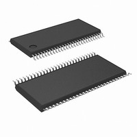
LM93CIMT/NOPB National Semiconductor, LM93CIMT/NOPB Datasheet - Page 27

LM93CIMT/NOPB
Manufacturer Part Number
LM93CIMT/NOPB
Description
IC HARDWARE MONITOR 56-TSSOP
Manufacturer
National Semiconductor
Datasheet
1.LM93CIMTNOPB.pdf
(92 pages)
Specifications of LM93CIMT/NOPB
Applications
Monitors
Interface
2-Wire SMBus
Voltage - Supply
3 V ~ 3.6 V
Package / Case
56-TSSOP
Mounting Type
Surface Mount
Lead Free Status / RoHS Status
Lead free / RoHS Compliant
Other names
*LM93CIMT
*LM93CIMT/NOPB
LM93CIMT
*LM93CIMT/NOPB
LM93CIMT
Available stocks
Company
Part Number
Manufacturer
Quantity
Price
Company:
Part Number:
LM93CIMT/NOPB
Manufacturer:
Intersil
Quantity:
169
15.0 Using The LM93
15.6 ERROR STATUS REGISTERS
The LM93 contains several error status registers for the
BMC side, and duplicated error status registers for the Host
side. These registers are used to reflect the state of all the
possible error conditions that the LM93 monitors.
The BMC/Host Error Status registers hold a set bit until the
event is cleared by software, even if the condition causing
the error event goes away.
To clear a bit in the Error Status registers, a ‘1’ has to be
written to the specific bit that is required to be cleared. If the
event that caused the error is no longer active then the bit is
cleared.
Clearing a bit in a BMC Error Status register does not clear
the corresponding bit in the Host Error Status register or vise
versa.
15.6.1 ASF Mode
In order for the LM93 part to act as a legacy sensor (6.1.2 of
ASF spec DSP0114 rev 2) and to easily bolt up to the SMBus
of an ASF capable NIC chip, the treatment of the Error
Status registers needs to change.
The LM93 can be placed into ASF mode by setting the
appropriate bit in the LM93 Status/Control register. Once this
bit is set, the BMC Error Status registers become read-to-
clear. Writing a ‘1’ to clear a particular bit is also allowed in
ASF mode. The Host Error Status registers are not effected
by ASF mode.
Channel
10
12
13
14
15
16
17
18
19
11
#
1
2
3
4
5
6
7
8
9
Temp Zone 1
Temp Zone 2
Temp Zone 3
AIN1
AIN2
AIN3
AIN4
AIN5
AIN6
AIN7
AIN8
AIN9
AIN10
AIN11
AIN12
AIN13
AIN14
AIN15
AIN16
Input
Remote Diode 1 Temp
Reading
Remote Diode 2 Temp
Reading
Internal Temperature
Reading
+12V1
+12V2
+12V3
FSB_Vtt
3GIO/PXH/MCH_Core
ICH_Core
CPU_1Vccp
CPU2_Vccp
3.3V
+5V
SCSI_Core
Mem_Core
Mem_Vtt
GBIT_Core
−12V
3.3V SB V
Typical Assignment
(Continued)
DD
Supply Rail
27
15.7 MASKING, ERROR STATUS AND ALERT
Masking is always applied to bits in the HOST and BMC
Error Status registers. If an event is masked, the corre-
sponding error bit in the HOST or BMC Error Status registers
is prevented from ever being set. As a result, this prevents
the event from ever causing ALERT to be asserted. Masking
an event does not clear its associated Error Status bit if it is
currently set.
Voltage errors are masked by writing a high voltage limit
value of FFh. This is the default high limit for all voltages.
Temperature errors are masked by writing a high tempera-
ture limit value of 80h. This is the default high limit for all
temperatures. Masking a temperature channel masks both
temperature errors and diode fault errors.
The GPI Mask register allows GPI errors to be masked. Any
bits that are set in this register mask events for the corre-
sponding GPIO_x pin.
User PROCHOT status is not really an error but it can be
used to notify the user of processor throttling past a preset
USER limit. A user limit of FFh acts as the mask for this
register.
PROCHOT thresholds cannot be masked. It is important to
note though, that these error bits do not cause BMC_ERR,
HOST_ERR, or ALERT to be asserted under any condition.
Fan tach errors are masked if the tach limit for the given tach
is set to FFh .
SCSI_TERMx errors and VRDx_HOT errors can be masked
by setting the appropriate bit in the VRD THERMTRIP and
SCSI_TERM Error Mask register.
When the LM93 powers up, the ALERT output is disabled.
The ALERT output can be enabled by setting the ALERT_EN
bit in the LM93 Configuration register.
In addition the manual masking options, the LM93 also
masks some errors depending on the sleep state of the
system. The sleep state of the system is communicated to
the LM93 by writing to the Sleep State Control register.
Some types of error events are always masked in certain
sleep modes. Some types of error events are optionally
masked in certain sleep modes if their sleep mask register
bit is set. Refer to the register descriptions for more informa-
tion.
15.8 LAYOUT AND GROUNDING
Analog components such as voltage dividers should be
physically located as close as possible to the LM93.
The LM93 bypass capacitors, the parallel combination of
100 pF, 10 µF (electrolytic or tantalum) and 0.1 µF (ceramic)
bypass capacitors must be connected between power pin
(pin 39) and ground, and should be located as close as
possible to the LM93. The 100 pF capacitor should be
placed closest to the power pin.
15.9 THERMAL DIODE APPLICATION
To measure temperature external to the LM93, we need to
use a remote discrete diode to sense the temperature of
external objects or ambient air. Remember that the tempera-
ture of a discrete diode is effected, and often dominated, by
the temperature of its leads.
Most silicon diodes do not lend themselves well to this
application. It is recommended that a MMBT3904 transistor
type base emitter junction be used with the collector tied to
the base.
Error
bits
associated
with
the
www.national.com
predefined


