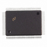
DP83840AVCE National Semiconductor, DP83840AVCE Datasheet - Page 50

DP83840AVCE
Manufacturer Part Number
DP83840AVCE
Description
IC ETHERNET PHYS LAYER 100-PQFP
Manufacturer
National Semiconductor
Datasheet
1.DP83840AVCE.pdf
(89 pages)
Specifications of DP83840AVCE
Controller Type
Ethernet Controller, 10Base-T
Interface
IEEE 802.3af
Voltage - Supply
4.75 V ~ 5.25 V
Current - Supply
335mA
Operating Temperature
0°C ~ 70°C
Mounting Type
Surface Mount
Package / Case
100-MQFP, 100-PQFP
Lead Free Status / RoHS Status
Contains lead / RoHS non-compliant
Other names
*DP83840AVCE
Available stocks
Company
Part Number
Manufacturer
Quantity
Price
Company:
Part Number:
DP83840AVCE
Manufacturer:
Texas Instruments
Quantity:
10 000
Part Number:
DP83840AVCE
Manufacturer:
NS/国半
Quantity:
20 000
Version A
4.0 Registers
4.11 RECEIVE ERROR COUNTER REGISTER (RECR)
Address 15h
4.12 SILICON REVISION REGISTER (SRR)
Address 16h
4.13 PCS CONFIGURATION REGISTER (PCR)
Address 17h
15:0
15:0
Bit
Bit
Bit
15
14
13
12
DESCR_TO_SEL
DESCR_TO_DIS
RXERCNT[15:0]
SIREV[15:0]
REPEATER
Bit Name
Bit Name
Bit Name
NRZI_EN
(Continued)
<0000h>, RW/SC RX_ER COUNTER: This 16-bit counter is incremented for each packet
<0001h>, RO/P
(Pin #47), RW
Default
Default
Default
1, RW
0, RW
0, RW
in which a receive error is detected. If there are one or more receiver
error conditions during a valid packet reception (i.e. no collision occurred
during packet reception), the counter is incremented once at the end of
packet reception. This counter rolls over when full.
Silicon Revision Number: This register contains the DP83840A
device’s silicon revision code. The value will be incremented for each
new major revision of the silicon.
NRZI ENABLE:
1 = NRZI encoding and decoding of the 100Mb/s transmit and receive
data streams
0 = NRZI encoding and decoding disabled
DESCRAMBLER TIMEOUT SELECT:
1 = Descrambler Timer set to 2 ms
0 = Descrambler Timer set to 722 s
The Descrambler Timer selects the interval over which a minimum
number of IDLES are required to be received to maintain descrambler
synchronization. The default time of 722
compliant applications.
A timer timeout indicates a loss of descrambler synchronization which
causes the descrambler to restart its operation by immediately looking
for IDLEs.
The 2 ms option allows applications with Maximum Transmission Units
(packet sizes) larger than IEEE 802.3 to maintain descrambler
synchronization
applications.)
DESCRAMBLER TIMEOUT DISABLE:
1 = Timeout timer in the descrambler section of the receiver disabled
0 = Timeout timer enabled
1 = Repeater mode
0 = Node mode
In repeater mode the Carrier Sense (CRS) output from the DP83840A is
asserted due to receive activity only. In node mode, and not configured
for Full Duplex operation, CRS is asserted due to either receive or
transmit activity.
The value of the REPEATER pin 47 (set by a pull-up or pull-down
resistor, typically 4.7 k ) is latched into this bit at power-up/reset.
REPEATER/NODE MODE:
50
(i.e.
Token
National Semiconductor
Description
Description
Description
Ring/Fast-Ethernet
s supports 100BASE-X
switch/router


