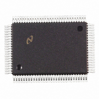
DP83840AVCE National Semiconductor, DP83840AVCE Datasheet - Page 32

DP83840AVCE
Manufacturer Part Number
DP83840AVCE
Description
IC ETHERNET PHYS LAYER 100-PQFP
Manufacturer
National Semiconductor
Datasheet
1.DP83840AVCE.pdf
(89 pages)
Specifications of DP83840AVCE
Controller Type
Ethernet Controller, 10Base-T
Interface
IEEE 802.3af
Voltage - Supply
4.75 V ~ 5.25 V
Current - Supply
335mA
Operating Temperature
0°C ~ 70°C
Mounting Type
Surface Mount
Package / Case
100-MQFP, 100-PQFP
Lead Free Status / RoHS Status
Contains lead / RoHS non-compliant
Other names
*DP83840AVCE
Available stocks
Company
Part Number
Manufacturer
Quantity
Price
Company:
Part Number:
DP83840AVCE
Manufacturer:
Texas Instruments
Quantity:
10 000
Part Number:
DP83840AVCE
Manufacturer:
NS/国半
Quantity:
20 000
Version A
The Manchester encoder accepts NRZ data from the
controller or repeater, encodes the data to Manchester,
and transmits it differentially to the transceiver, through the
differential transmit driver.
The Manchester decoder receives Manchester data from
the transceiver, converts it to NRZ data and recovers clock
pulses for synchronous data transfer to the controller or
repeater.
The collision monitor indicates to the controller the
presence of a valid 10 MHz collision signal.
3.7.13.1 Manchester Encoder and differential driver
The encoder begins operation when the Transmit Enable
input (TX_EN) goes high and converts the NRZ data to
pre-emphasized Manchester data for the transceiver. For
the duration of TXE remaining high, the Transmit Data
(TXD) is encoded for the transmit-driver pair (TXU+/- or
TXS+/-). TXD must be valid on the rising edge of Transmit
Clock (TXC). Transmission ends when TX_EN deasserts.
The last transition is always positive; it occurs at the center
of the bit cell if the last bit is a one, or at the end of the bit
cell if the last bit is a zero.
3.7.13.2 Manchester Decoder
The decoder consists of a differential receiver and a PLL to
separate a Manchester encoded data stream into internal
clock signals and data. The differential input must be
externally terminated with either a differential 100
differential 150
either UTP or STP cable respectively. Refer to Figure 16
for further detail.
3.0 Functional Description
R
R
termination network to accommodate
GND
Vcc
R
R
(Continued)
REQ
RTX
FIGURE 16. REQ and RTX Operation
32
or
Fixed
Current
Source
Fixed
Current
Source
The decoder detects the end of a frame when no more
mid-bit transitions are detected. Within one and a half bit
times after the last bit, carrier sense is de-asserted.
Receive clock stays active for five more bit times after CRS
goes low, to guarantee the receive timings of the controller
or repeater.
3.7.14 REQ and RTX
These pins allow for the direct control of both the pre-
emphasis (REQ) and the transmit amplitude (RTX) of the
10BASE-T transmit signal. These pins should normally be
left floating, however, in applications where lower transmit
amplitudes are required, these pins should be pulled-down
to ground resistively. Conversely, for applications that
require higher transmit amplitudes, these pins should be
pulled-up to Vcc resistively. Figure 16 provides a simplified
functional diagram.
Some experimentation is required in order to fully evaluate
the extent of transmit amplitude (and corresponding pre-
emphasis) variation due to the system to system variations
in external components (e.g. transformers and termination
networks). It is important to use the same resistor value for
both RTX and REQ (pulled to the same rail) in order to
allow the pre-emphasis to track the transmit amplitude.
In general terms, a value of approximately 50K
pins (either pulled-up or pulled-down) will result in a
transmit amplitude (and pre-emphasis) change on the
order
recommended.
of
5%
National Semiconductor
to
10%.
Transmit
Amplitude
Control
Transmit
Pre-emphasis
Control
Again,
experimentation
for these
is


