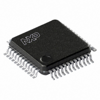
UCB1400BE,151 NXP Semiconductors, UCB1400BE,151 Datasheet - Page 38

UCB1400BE,151
Manufacturer Part Number
UCB1400BE,151
Description
IC AUDIO CODEC 3.3V 48-LQFP
Manufacturer
NXP Semiconductors
Type
Audio Codec '97r
Datasheet
1.UCB1400BEFE.pdf
(63 pages)
Specifications of UCB1400BE,151
Package / Case
48-LQFP
Data Interface
Serial
Resolution (bits)
20 b
Number Of Adcs / Dacs
2 / 2
Sigma Delta
No
S/n Ratio, Adcs / Dacs (db) Typ
97 / 91
Voltage - Supply, Analog
3 V ~ 3.6 V
Voltage - Supply, Digital
3 V ~ 3.6 V
Operating Temperature
-40°C ~ 85°C
Mounting Type
Surface Mount
Mounting Style
SMD/SMT
Lead Free Status / RoHS Status
Lead free / RoHS Compliant
Other names
935269304151
UCB1400BE-SNXP
UCB1400BE-SNXP
UCB1400BE-SNXP
UCB1400BE-SNXP
Available stocks
Company
Part Number
Manufacturer
Quantity
Price
Company:
Part Number:
UCB1400BE,151
Manufacturer:
NXP Semiconductors
Quantity:
10 000
Philips Semiconductors
9397 750 09611
Product data
12.7 Power-down Control/Status register (index 0x26)
Table 23:
Register address: 0x26; default: 000X
Table 24:
This read/write register is used to program power-down states and monitor
subsystem readiness. The lower half of this register is read only status, a ‘1’
indicating that the subsection is ‘ready’. ‘Ready’ is defined as the subsection able to
perform in its nominal state. When this register is written, the bit values that come in
on AC-link will have no effect on read-only bits 0 - 7.
When the ‘Codec Ready’ indicator bit (SDATA_IN slot 0, bit 15) is a 1, it indicates that
the UCB1400 control and status registers are in a fully operational state. The AC ’97
Controller must further probe this Power-down Control/Status register to determine
exactly which subsections, if any, are ready.
Bit
D15 - D14
D13
D12
D11
D10
D9
D8
D7 - D4
D3
D2
D1
D0
Bit
Symbol
Bit
Symbol
Power-down Control/Status register
Description of Power-down Control/Status register bits
D15
D7
X
X
Symbol
X
PR5
PR4
PR3
X
PR1
PR0
X
REF
X
DAC
ADC
Rev. 02 — 21 June 2002
D14
D6
X
X
Type
R
RW
RW
RW
R
RW
RW
R
R
R
R
R
PR5
D13
D5
X
Description
Reserved.
Internal clock disable.
Digital interface (AC-link) power-down (external
clock off).
Audio V
Reserved.
Audio DAC and output path power-down.
Audio ADC and input path power-down.
Reserved.
Audio V
Reserved.
Audio DAC section ready to accept data.
Audio ADC section ready to transmit data.
PR4
Audio codec with touch screen controller
D12
D4
X
REF
REF
power-down.
up to nominal level.
REF
and power management monitor
PR3
D11
D3
© Koninklijke Philips Electronics N.V. 2002. All rights reserved.
D10
D2
X
X
UCB1400
PR1
DAC
D9
D1
ADC
38 of 63
PR0
D8
D0


