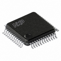
UCB1400BE,151 NXP Semiconductors, UCB1400BE,151 Datasheet - Page 14

UCB1400BE,151
Manufacturer Part Number
UCB1400BE,151
Description
IC AUDIO CODEC 3.3V 48-LQFP
Manufacturer
NXP Semiconductors
Type
Audio Codec '97r
Datasheet
1.UCB1400BEFE.pdf
(63 pages)
Specifications of UCB1400BE,151
Package / Case
48-LQFP
Data Interface
Serial
Resolution (bits)
20 b
Number Of Adcs / Dacs
2 / 2
Sigma Delta
No
S/n Ratio, Adcs / Dacs (db) Typ
97 / 91
Voltage - Supply, Analog
3 V ~ 3.6 V
Voltage - Supply, Digital
3 V ~ 3.6 V
Operating Temperature
-40°C ~ 85°C
Mounting Type
Surface Mount
Mounting Style
SMD/SMT
Lead Free Status / RoHS Status
Lead free / RoHS Compliant
Other names
935269304151
UCB1400BE-SNXP
UCB1400BE-SNXP
UCB1400BE-SNXP
UCB1400BE-SNXP
Available stocks
Company
Part Number
Manufacturer
Quantity
Price
Company:
Part Number:
UCB1400BE,151
Manufacturer:
NXP Semiconductors
Quantity:
10 000
Philips Semiconductors
9397 750 09611
Product data
8.4 Accessing the UCB1400
Waking up the AC-link:
power, halted mode. Regardless of the method, it is the AC ’97 Controller that
performs the wake-up task.
AC-link protocol provides for a ‘Cold AC ’97 Reset’, and a ‘Warm AC ’97 Reset’. The
current power-down state would ultimately dictate which form of AC ’97 reset is
appropriate. Unless a ‘cold’ or ‘register’ reset (a write to the Reset register) is
performed, wherein the UCB1400 registers are initialized to their default values,
registers are required to keep state during all power-down modes.
Once powered down, re-activation of the AC-link via re-assertion of the SYNC signal
must not occur for a minimum of four audio frame times following the frame in which
the power-down was triggered. When AC-link powers-up, it indicates readiness via
the Codec Ready bit (input slot 0, bit 15).
Cold AC ’97 reset:
specified time. By driving RESET LOW, all UCB1400 control registers will be
initialized to their default power-on reset values. BIT_CLK and SDATA_OUT will be
activated, or re-activated as the case may be. RESET is an asynchronous input to the
UCB1400.
Warm AC ’97 reset:
the current AC ’97 register values. A warm reset is signaled, in the absence of
BIT_CLK, by driving SYNC HIGH for a minimum of 1 s.
Within normal audio frames, SYNC is a synchronous input to the UCB1400. However,
in the absence of BIT_CLK, SYNC is treated as an asynchronous input used in the
generation of a warm reset to the UCB1400.
The UCB1400 must not respond with the activation of BIT_CLK until SYNC has
been sampled LOW again by the UCB1400. This will preclude the false detection of a
new audio frame.
The UCB1400 supports only primary codec configuration. Typically, the UCB1400
expects a 24.576 MHz crystal across the XTL_IN and XTL_OUT pins. Alternatively,
an external 24.576 MHz clock can be applied to XTL_IN.
Table 4:
Bit
15
14
13
12-3
2
1-0
AC-link audio output frame slot 0 bit allocation
Description
Frame valid
Slot 1 valid command address bit (primary codec only)
Slot 2 valid command data bit (primary codec only)
Slot 3-12 valid bits as defined by AC ’97 Component Specification
Reserved (set to 0)
2-bit codec ID field
00 reserved for primary
01, 10, 11 indicate secondary
Rev. 02 — 21 June 2002
A cold reset is achieved by asserting RESET for the minimum
A warm AC ’97 reset will re-activate the AC-link without altering
There are two methods for bringing the AC-link out of a low
Audio codec with touch screen controller
and power management monitor
© Koninklijke Philips Electronics N.V. 2002. All rights reserved.
UCB1400
14 of 63


