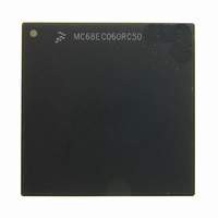
MC68EC060RC50 Freescale Semiconductor, MC68EC060RC50 Datasheet - Page 19

MC68EC060RC50
Manufacturer Part Number
MC68EC060RC50
Description
IC MPU 32BIT 50MHZ 206-PGA
Manufacturer
Freescale Semiconductor
Specifications of MC68EC060RC50
Processor Type
M680x0 32-Bit
Speed
50MHz
Voltage
3.3V
Mounting Type
Surface Mount
Package / Case
206-PGA
Family Name
M68000
Device Core
ColdFire
Device Core Size
32b
Frequency (max)
50MHz
Instruction Set Architecture
RISC
Supply Voltage 1 (typ)
3.3V
Operating Supply Voltage (max)
3.465V
Operating Supply Voltage (min)
3.135V
Operating Temp Range
0C to 110C
Operating Temperature Classification
Commercial
Mounting
Through Hole
Pin Count
206
Package Type
PGA
Lead Free Status / RoHS Status
Contains lead / RoHS non-compliant
Features
-
Lead Free Status / Rohs Status
Compliant
Available stocks
Company
Part Number
Manufacturer
Quantity
Price
Company:
Part Number:
MC68EC060RC50
Manufacturer:
NXP
Quantity:
1 746
- Current page: 19 of 416
- Download datasheet (2Mb)
7-38
7-39
7-40
7-41
7-42
7-43
7-44
7-45
7-46
7-47
7-48
7-49
7-50
7-51
7-52
8-1
8-2
8-3
8-4
8-5
8-6
9-1
9-2
9-3
9-4
9-5
9-6
9-7
9-8
9-9
9-10
9-11
9-12
9-13
11-1
11-2
11-3
11-4
11-5
11-6
11-7
11-8
11-9
11-10
11-11
MOTOROLA
Line Read Access Bus Cycle Terminated with TEA Timing............................. 7-49
Retry Read Bus Cycle Timing .......................................................................... 7-50
Line Write Retry Bus Cycle Timing................................................................... 7-51
MC68040-Arbitration Protocol State Diagram .................................................. 7-57
MC68060-Arbitration Protocol State Diagram .................................................. 7-64
Processor Bus Request Timing........................................................................ 7-67
Arbitration During Relinquish and Retry Timing ............................................... 7-68
Implicit Bus Ownership Arbitration Timing........................................................ 7-69
Effect of BGR on Locked Sequences............................................................... 7-70
Snooped Bus Cycle.......................................................................................... 7-71
Initial Power-On Reset Timing.......................................................................... 7-72
Normal Reset Timing........................................................................................ 7-73
Data Bus Usage During Reset ......................................................................... 7-74
Acknowledge Termination Ignore State Example ............................................ 7-75
Extra Data Write Hold Example........................................................................ 7-77
General Exception Processing Flowchart .......................................................... 8-2
General Form of Exception Stack Frame ........................................................... 8-3
Interrupt Recognition Examples ....................................................................... 8-13
Interrupt Exception Processing Flowchart........................................................ 8-15
Reset Exception Processing Flowchart............................................................ 8-16
Fault Status Long-Word Format ....................................................................... 8-22
JTAG Test Logic Block Diagram ........................................................................ 9-3
JTAG Idcode Register Format............................................................................ 9-7
Output Pin Cell (O.Pin)....................................................................................... 9-8
Observe-Only Input Pin Cell (I.Obs)................................................................... 9-8
Input Pin Cell (I.Pin) ........................................................................................... 9-9
Output Control Cell (IO.Ctl) ................................................................................ 9-9
General Arrangement of Bidirectional Pin Cells ............................................... 9-10
JTAG Bypass Register ..................................................................................... 9-15
Circuit Disabling IEEE Standard 1149.1........................................................... 9-16
Debug Command Interface Schematic ............................................................ 9-25
Interface Timing................................................................................................ 9-26
Transition from JTAG to Debug Mode Timing Diagram ................................... 9-34
Transition from Debug to JTAG Mode Timing Diagram ................................... 9-35
Linear Voltage Regulator Solution.................................................................... 11-7
LTC1147 Voltage Regulator Solution............................................................... 11-8
LTC1148 Voltage Regulator Solution............................................................... 11-9
MAX767 Voltage Regulator Solution.............................................................. 11-10
MC68040 Address Hold Time ........................................................................ 11-11
MC68060 Address Hold Time ........................................................................ 11-12
MC68060 Address Hold Time Fix .................................................................. 11-12
Simple CLK Generation.................................................................................. 11-14
Generic CLK Generation ................................................................................ 11-14
MC68040 BCLK to CLKEN Relationship........................................................ 11-15
DRAM Timing Analysis................................................................................... 11-15
M68060 USER’S MANUAL
List of Illustrations
xxi
Related parts for MC68EC060RC50
Image
Part Number
Description
Manufacturer
Datasheet
Request
R
Part Number:
Description:
Manufacturer:
Freescale Semiconductor, Inc
Datasheet:
Part Number:
Description:
Manufacturer:
Freescale Semiconductor, Inc
Datasheet:
Part Number:
Description:
Manufacturer:
Freescale Semiconductor, Inc
Datasheet:
Part Number:
Description:
Manufacturer:
Freescale Semiconductor, Inc
Datasheet:
Part Number:
Description:
Manufacturer:
Freescale Semiconductor, Inc
Datasheet:
Part Number:
Description:
Manufacturer:
Freescale Semiconductor, Inc
Datasheet:
Part Number:
Description:
Manufacturer:
Freescale Semiconductor, Inc
Datasheet:
Part Number:
Description:
Manufacturer:
Freescale Semiconductor, Inc
Datasheet:
Part Number:
Description:
Manufacturer:
Freescale Semiconductor, Inc
Datasheet:
Part Number:
Description:
Manufacturer:
Freescale Semiconductor, Inc
Datasheet:
Part Number:
Description:
Manufacturer:
Freescale Semiconductor, Inc
Datasheet:
Part Number:
Description:
Manufacturer:
Freescale Semiconductor, Inc
Datasheet:
Part Number:
Description:
Manufacturer:
Freescale Semiconductor, Inc
Datasheet:
Part Number:
Description:
Manufacturer:
Freescale Semiconductor, Inc
Datasheet:
Part Number:
Description:
Manufacturer:
Freescale Semiconductor, Inc
Datasheet:


