5535032-5 TE Connectivity, 5535032-5 Datasheet - Page 9
5535032-5
Manufacturer Part Number
5535032-5
Description
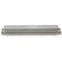
ASSY,RECEPTACLE,EUROCARD,TYPE C,LEAD-FRE
Manufacturer
TE Connectivity
Series
5535032 Seriesr
Type
Type Cr
Datasheet
1.148384-5.pdf
(18 pages)
Specifications of 5535032-5
Pitch Spacing
2.54mm
No. Of Contacts
96
Gender
Receptacle
No. Of Rows
3
Rows Loaded
A + B + C
Contact Termination
Through Hole
Contact Material
Brass
Contact Plating
Gold
Approval
RoHS Compliant
Number Of Rows
3
Number Of Positions / Contacts
96
Termination Style
Solder Pin
Pitch
2.54 mm
Connector Type
Connector Assembly
Pcb Mount Retention
With
Pcb Mounting Orientation
Vertical
Pcb Thickness (minimum) (mm [in])
1.57 [0.062]
Post Type
Compliant Post
Size
Standard
Make First / Break Last
No
Bus Type
FUTUREBUS, MULTIBUS (II), NUBUS, VMEbus, VXIBus
Din Level
II
Mounting Ears
With
Toolless (flat Rock)
Yes
Termination Post Length (mm [in])
4.83 [0.190]
Solder Tail Contact Plating
Tin
Centerline (mm [in])
2.54 [0.100]
Number Of Positions
96
Pcb Mount Retention Type
Compliant Posts
Contact Cross Section (mm [in])
0.30 x 0.61 [.012 x .024]
Contact Type
Socket
Contact Base Material
Copper Alloy
Contact Plating, Mating Area, Material
DIN 41612 Class 2
Connector Style
Receptacle
Housing Material
Polymer
Ul Flammability Rating
UL 94V-0
Flux-tight Coating
Without
Rohs/elv Compliance
RoHS compliant, ELV compliant
Lead Free Solder Processes
Not relevant for lead free process
Rohs/elv Compliance History
Always was RoHS compliant
Applies To
Printed Circuit Board
High Temperature Housing
No
Lead Free Status / Rohs Status
Details


3.5. Wrap- Type Contacts
The wrap--type contacts available in these connectors will accommodate one or two wire wrap applications. It
is recommended that 8 to 10 turns of solid wire be wrapped when using wire size 32 AWG, 7 to 9 turns when
using wire size 30 or 28 AWG, and 6 to 7 turns when using wire size 26 AWG. The wire must be tightly
wrapped to achieve reliable wrap--type terminations. See Figure 6.
3.6. Ancillary Items
Rev G
Guide Bracket
(Typ)
A. Guide Brackets
Various types of guide brackets have been designed for application to Type C connectors. The guide
bracket is mounted onto the pc board to help properly guide the mating connector onto the pin or
receptacle connector. The bracket is also designed to attach to the connector with the mounting screws
and nuts supplied with the guide brackets to ensure a stable application. See Figure 7.
B. Dust Covers
Dust covers are used to protect the mating face of connectors that are not mated. The cover must be
aligned with the mating face of the connector and pressed into position. The covers are available for Type
C connectors 64-- and 96--position. See Figure 8.
Mounting
Hardware
PC Board
Wire Wrap
Application
(Ref)
PC Board
Figure 6
Figure 7
Type C
Connector
(Typ)
Mating
Connector
(Ref)
Mounting
Hardware
114- 9014
9 of 18
Related parts for 5535032-5
Image
Part Number
Description
Manufacturer
Datasheet
Request
R


Part Number:
Description:
Printers THERMAL PRINTER HS-SLEEVE MARKER
Manufacturer:
TE Connectivity

Part Number:
Description:
High Speed / Modular Connectors 30P HEADER ASSY
Manufacturer:
TE Connectivity
Datasheet:

Part Number:
Description:
High Speed / Modular Connectors REC 6X005P R/A LT B-PLANE HS3
Manufacturer:
TE Connectivity
Datasheet:

Part Number:
Description:
High Speed / Modular Connectors 2MM HM RCPT 50P R/A AU
Manufacturer:
TE Connectivity
Datasheet:

Part Number:
Description:
High Speed / Modular Connectors 2MM HM RCPT 50P R/A AU
Manufacturer:
TE Connectivity
Datasheet:


Part Number:
Description:
Manufacturer:
TE Connectivity
Datasheet:


Part Number:
Description:
Manufacturer:
TE Connectivity
Datasheet:

Part Number:
Description:
Manufacturer:
TE Connectivity
Datasheet:

Part Number:
Description:
Manufacturer:
TE Connectivity
Datasheet: