5535032-5 TE Connectivity, 5535032-5 Datasheet - Page 3
5535032-5
Manufacturer Part Number
5535032-5
Description
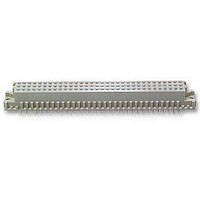
ASSY,RECEPTACLE,EUROCARD,TYPE C,LEAD-FRE
Manufacturer
TE Connectivity
Series
5535032 Seriesr
Type
Type Cr
Datasheet
1.148384-5.pdf
(18 pages)
Specifications of 5535032-5
Pitch Spacing
2.54mm
No. Of Contacts
96
Gender
Receptacle
No. Of Rows
3
Rows Loaded
A + B + C
Contact Termination
Through Hole
Contact Material
Brass
Contact Plating
Gold
Approval
RoHS Compliant
Number Of Rows
3
Number Of Positions / Contacts
96
Termination Style
Solder Pin
Pitch
2.54 mm
Connector Type
Connector Assembly
Pcb Mount Retention
With
Pcb Mounting Orientation
Vertical
Pcb Thickness (minimum) (mm [in])
1.57 [0.062]
Post Type
Compliant Post
Size
Standard
Make First / Break Last
No
Bus Type
FUTUREBUS, MULTIBUS (II), NUBUS, VMEbus, VXIBus
Din Level
II
Mounting Ears
With
Toolless (flat Rock)
Yes
Termination Post Length (mm [in])
4.83 [0.190]
Solder Tail Contact Plating
Tin
Centerline (mm [in])
2.54 [0.100]
Number Of Positions
96
Pcb Mount Retention Type
Compliant Posts
Contact Cross Section (mm [in])
0.30 x 0.61 [.012 x .024]
Contact Type
Socket
Contact Base Material
Copper Alloy
Contact Plating, Mating Area, Material
DIN 41612 Class 2
Connector Style
Receptacle
Housing Material
Polymer
Ul Flammability Rating
UL 94V-0
Flux-tight Coating
Without
Rohs/elv Compliance
RoHS compliant, ELV compliant
Lead Free Solder Processes
Not relevant for lead free process
Rohs/elv Compliance History
Always was RoHS compliant
Applies To
Printed Circuit Board
High Temperature Housing
No
Lead Free Status / Rohs Status
Details


2.5. Instructional Material
Available instruction sheets (408--series) and customer manuals (409--series) contain detailed assembly
instructions and repair procedures for product and tooling. Documents available which pertain to Eurocard
connectors are:
2.6. Manuals
Manual 402--40 is available upon request and can be used as a guide in soldering. This manual provides
information on various flux types and characteristics along with the commercial designation and flux removal
procedures. A checklist is included in the manual as a guide for information on soldering problems.
3. REQUIREMENTS
3.1. PC Board
Rev G
408--9027
408--9623
408--9740
408--9894
A. Thickness
B. Layout
The suggested pc board layout should be as specified in Figure 2.
1. Connectors with ACTION PIN contacts are available in two designs: one for pc boards with a
minimum thickness of 1.57 mm [.062 in.] and one for pc boards with a minimum thickness 2.36 mm
[.093 in.].
2. Connectors with solder tines or ACTION PIN thin stock contacts require a minimum pc board
thickness of 1.57 mm [.062 in.].
Adapter Kit for Greenerd Frame Assembly
Seating Tool 535072--1 (for Type C Receptacle Connectors and Seating Tool 148090--[ ] for
Type M Receptacle Connectors)
Seating Tools 768211--[ ] (for Type R Connectors with ACTION PIN Contacts)
Programmable Seating Tools 768216--[ ] (for Type R Connectors with MFBL Contacts)
114- 9014
3 of 18
Related parts for 5535032-5
Image
Part Number
Description
Manufacturer
Datasheet
Request
R


Part Number:
Description:
Printers THERMAL PRINTER HS-SLEEVE MARKER
Manufacturer:
TE Connectivity

Part Number:
Description:
High Speed / Modular Connectors 30P HEADER ASSY
Manufacturer:
TE Connectivity
Datasheet:

Part Number:
Description:
High Speed / Modular Connectors REC 6X005P R/A LT B-PLANE HS3
Manufacturer:
TE Connectivity
Datasheet:

Part Number:
Description:
High Speed / Modular Connectors 2MM HM RCPT 50P R/A AU
Manufacturer:
TE Connectivity
Datasheet:

Part Number:
Description:
High Speed / Modular Connectors 2MM HM RCPT 50P R/A AU
Manufacturer:
TE Connectivity
Datasheet:


Part Number:
Description:
Manufacturer:
TE Connectivity
Datasheet:


Part Number:
Description:
Manufacturer:
TE Connectivity
Datasheet:

Part Number:
Description:
Manufacturer:
TE Connectivity
Datasheet:

Part Number:
Description:
Manufacturer:
TE Connectivity
Datasheet: