5535032-5 TE Connectivity, 5535032-5 Datasheet - Page 13
5535032-5
Manufacturer Part Number
5535032-5
Description
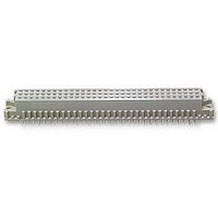
ASSY,RECEPTACLE,EUROCARD,TYPE C,LEAD-FRE
Manufacturer
TE Connectivity
Series
5535032 Seriesr
Type
Type Cr
Datasheet
1.148384-5.pdf
(18 pages)
Specifications of 5535032-5
Pitch Spacing
2.54mm
No. Of Contacts
96
Gender
Receptacle
No. Of Rows
3
Rows Loaded
A + B + C
Contact Termination
Through Hole
Contact Material
Brass
Contact Plating
Gold
Approval
RoHS Compliant
Number Of Rows
3
Number Of Positions / Contacts
96
Termination Style
Solder Pin
Pitch
2.54 mm
Connector Type
Connector Assembly
Pcb Mount Retention
With
Pcb Mounting Orientation
Vertical
Pcb Thickness (minimum) (mm [in])
1.57 [0.062]
Post Type
Compliant Post
Size
Standard
Make First / Break Last
No
Bus Type
FUTUREBUS, MULTIBUS (II), NUBUS, VMEbus, VXIBus
Din Level
II
Mounting Ears
With
Toolless (flat Rock)
Yes
Termination Post Length (mm [in])
4.83 [0.190]
Solder Tail Contact Plating
Tin
Centerline (mm [in])
2.54 [0.100]
Number Of Positions
96
Pcb Mount Retention Type
Compliant Posts
Contact Cross Section (mm [in])
0.30 x 0.61 [.012 x .024]
Contact Type
Socket
Contact Base Material
Copper Alloy
Contact Plating, Mating Area, Material
DIN 41612 Class 2
Connector Style
Receptacle
Housing Material
Polymer
Ul Flammability Rating
UL 94V-0
Flux-tight Coating
Without
Rohs/elv Compliance
RoHS compliant, ELV compliant
Lead Free Solder Processes
Not relevant for lead free process
Rohs/elv Compliance History
Always was RoHS compliant
Applies To
Printed Circuit Board
High Temperature Housing
No
Lead Free Status / Rohs Status
Details


3.8. Soldering
Connectors with solder contacts can be mounted on and secured to a pc board by hand soldering or wave
soldering techniques.
ALPHA, BIOACT, CARBITOL, KESTER, and LONCOTERGE are trademarks of their respective owners.
Rev G
CAUTION
C. Mating Conditions
To ensure reliable connections and prevent unnecessary damage to connectors, refer to the
recommended vertical alignment and offset tolerances shown in Figure 11.
A. Flux Selection
Solder tines and pc board attaching hardware must be fluxed prior to soldering. Selection of the flux will
depend on the type of pc board used and other components that may be mounted on the board. Also, the
choice will have to be compatible with the wave solder line, manufacturing, and safety requirements.
B. Cleaning
Fluxes, residues, and activators must be removed. Cleaning procedures depend on the type of flux used
on the solder line. The following cleaning compounds and chemicals may be used to clean the connectors
without adverse affect on the housings and contacts. See Figure 12.
!
ALPHA 2110
BIOACT EC--7
Butyl CARBITOL
Isopropyl Alcohol
KESTER 5778
KESTER 5779
LONCOTERGE 520
LONCOTERGE 530
Terpene Solvent
DISCONNECT electrical current before mating or unmating connectors.
1.02 [.040]
NAME
Vertical Alignment
CLEANER
1.02 [.040]
Aqueous
Aqueous
Aqueous
Aqueous
Aqueous
Solvent
Solvent
Solvent
Solvent
TYPE
Figure 11
Figure 12
(Minutes)
TIME
TIME
1
5
1
5
5
5
5
5
5
+4_
Offset Tolerances
TEMPERATURE
TEMPERATURE
132_C [270_F]
100_C [212_F]
100_C [212_F]
100_C [212_F]
100_C [212_F]
100_C [212_F]
100_C [212_F]
100_C [212_F]
Ambient Room
(Maximum)
+2_
114- 9014
13 of 18
Related parts for 5535032-5
Image
Part Number
Description
Manufacturer
Datasheet
Request
R


Part Number:
Description:
Printers THERMAL PRINTER HS-SLEEVE MARKER
Manufacturer:
TE Connectivity

Part Number:
Description:
High Speed / Modular Connectors 30P HEADER ASSY
Manufacturer:
TE Connectivity
Datasheet:

Part Number:
Description:
High Speed / Modular Connectors REC 6X005P R/A LT B-PLANE HS3
Manufacturer:
TE Connectivity
Datasheet:

Part Number:
Description:
High Speed / Modular Connectors 2MM HM RCPT 50P R/A AU
Manufacturer:
TE Connectivity
Datasheet:

Part Number:
Description:
High Speed / Modular Connectors 2MM HM RCPT 50P R/A AU
Manufacturer:
TE Connectivity
Datasheet:


Part Number:
Description:
Manufacturer:
TE Connectivity
Datasheet:


Part Number:
Description:
Manufacturer:
TE Connectivity
Datasheet:

Part Number:
Description:
Manufacturer:
TE Connectivity
Datasheet:

Part Number:
Description:
Manufacturer:
TE Connectivity
Datasheet: