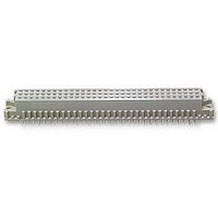
5535032-5 TE Connectivity, 5535032-5 Datasheet

5535032-5
Specifications of 5535032-5
Related parts for 5535032-5
5535032-5 Summary of contents
Page 1
... Multiple pin heights for connectors with make first, break last (MFBL) contacts and selective contact loading are available. When corresponding with TE Connectivity (TE) Personnel, use the terminology provided in this specification to facilitate your inquiries for information. Basic terms and features of these components are provided in Figure 1. ...
Page 2
PC Board Mount Power Contact ACTION PIN Thin Stock Contact Solder Cup Coaxial Cable Power Contact In- - Line Contact Coaxial Solder Tine Contact Type M Receptacle Connector 2. REFERENCE MATERIAL 2.1. Revision Summary The following revision summary of changes ...
Page 3
Instructional Material Available instruction sheets (408--series) and customer manuals (409--series) contain detailed assembly instructions and repair procedures for product and tooling. Documents available which pertain to Eurocard connectors are: 408--9027 Adapter Kit for Greenerd Frame Assembly 408--9623 Seating Tool ...
Page 4
Type B Pin Connector and Type Q Receptacle Connector “B” Type Q Pin Connector and Type B Receptacle Connector “B” Type R Pin Connector and Type C Receptacle Connector H See Figure Dim ...
Page 5
Type C Pin Connector and Type R Receptacle Connector (For Solder Tine Coaxial Connectors) (For Solder Tine Coaxial Connectors) H See Figure 3 Rev G Dim (Two x Dim. B) “A” (Number of Spaces x 2.54 [.100]) “A” ...
Page 6
H See Figure Dim (Two x Dim. B) “A” Three- - Row “C” Position (Ref) Four- - Row Position (Ref) Number of Spaces (Between Four- - Row Positions) x Dim. A Number of ...
Page 7
C. Hole Dimensions (Figure 3) Values specified in the following must be complied with to ensure proper performance. The drilled hole diameter and the copper plating thickness are of major importance and must be adhered to. Refer to Paragraph 3.1.A.1 ...
Page 8
No Special Tooling Required 5.05 +0.05 [.199 +.002] Mounting Ear Height 0.081 [.003] Standoff Spacing (Centerline- - to- - Centerline) 3.3. Mounting Hardware Connectors are designed to be secured to the pc board with commercially available M2.5 mounting screws and ...
Page 9
Wrap- Type Contacts The wrap--type contacts available in these connectors will accommodate one or two wire wrap applications recommended that turns of solid wire be wrapped when using wire size 32 AWG ...
Page 10
C. Shrouds Mating capabilities may be expanded by stacking connectors with the use of a shroud. Shrouds are used with all 48-- and 96--position, three--row, Type C connectors and all 48-- and 96--position, Type R connectors with ACTION PIN contacts ...
Page 11
B. Mating Dimensions Possible mating configurations are illustrated in Figure 10. The dimensions shown are for reference only when designing systems. Designated centerlines indicate mounting hole NOTE location. Refer to the applicable TE customer drawing for connector dimensions. i Type ...
Page 12
Type R Pin and Receptacle Connector D When connector types are mixed (for example, C and R), the connector circuit numbers will not match; for example, Position A1 of the pin connector will mate with Position A32 of the receptacle ...
Page 13
C. Mating Conditions To ensure reliable connections and prevent unnecessary damage to connectors, refer to the recommended vertical alignment and offset tolerances shown in Figure 11. DISCONNECT electrical current before mating or unmating connectors. CAUTION ! Vertical Alignment 1.02 [.040] ...
Page 14
Consideration must be given to toxicity and safety requirements recommended on the Material Safety Data Sheet DANGER furnished by the solvent manufacturer. If you have a particular solvent that is not listed, consult an TE Representative before using it on ...
Page 15
PC Board Support A pc board support (customer supplied) must be used for the seating of connectors. While many materials can be used for this, steel or cast aluminum is recommended. A. Multi- Layered PC Board Support A flat--plate ...
Page 16
Seating Tool Seating tools must be used in manual or power assist units with sufficient ram surface and the capability of applying insertion force per contact. The seating tools align the components for proper seating and are specifically designed ...
Page 17
Connector Replacement Tooling When entire Type C receptacle connectors and Type R pin connectors must be replaced, Eurocard Connector Removal Tool Kit 534611--1 should be used. Refer to Figure 16 and proceed as follows: DO NOT use this tool ...
Page 18
VISUAL AID Figure 17 shows a typical application of a Eurocard Connector. This illustration should be used by production personnel to ensure a correctly applied product. Applications which DO NOT appear correct should be inspected using the information in ...


