5535032-5 TE Connectivity, 5535032-5 Datasheet - Page 7
5535032-5
Manufacturer Part Number
5535032-5
Description
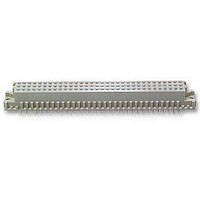
ASSY,RECEPTACLE,EUROCARD,TYPE C,LEAD-FRE
Manufacturer
TE Connectivity
Series
5535032 Seriesr
Type
Type Cr
Datasheet
1.148384-5.pdf
(18 pages)
Specifications of 5535032-5
Pitch Spacing
2.54mm
No. Of Contacts
96
Gender
Receptacle
No. Of Rows
3
Rows Loaded
A + B + C
Contact Termination
Through Hole
Contact Material
Brass
Contact Plating
Gold
Approval
RoHS Compliant
Number Of Rows
3
Number Of Positions / Contacts
96
Termination Style
Solder Pin
Pitch
2.54 mm
Connector Type
Connector Assembly
Pcb Mount Retention
With
Pcb Mounting Orientation
Vertical
Pcb Thickness (minimum) (mm [in])
1.57 [0.062]
Post Type
Compliant Post
Size
Standard
Make First / Break Last
No
Bus Type
FUTUREBUS, MULTIBUS (II), NUBUS, VMEbus, VXIBus
Din Level
II
Mounting Ears
With
Toolless (flat Rock)
Yes
Termination Post Length (mm [in])
4.83 [0.190]
Solder Tail Contact Plating
Tin
Centerline (mm [in])
2.54 [0.100]
Number Of Positions
96
Pcb Mount Retention Type
Compliant Posts
Contact Cross Section (mm [in])
0.30 x 0.61 [.012 x .024]
Contact Type
Socket
Contact Base Material
Copper Alloy
Contact Plating, Mating Area, Material
DIN 41612 Class 2
Connector Style
Receptacle
Housing Material
Polymer
Ul Flammability Rating
UL 94V-0
Flux-tight Coating
Without
Rohs/elv Compliance
RoHS compliant, ELV compliant
Lead Free Solder Processes
Not relevant for lead free process
Rohs/elv Compliance History
Always was RoHS compliant
Applies To
Printed Circuit Board
High Temperature Housing
No
Lead Free Status / Rohs Status
Details


3.2. Housing Features
Surface Finish
HASL Sn Pb
Immersion Sn
OSP
Immersion Au/Ni
Immersion Ag
Rev G
Solder Tine Plated--Through
CONTACT
ACTION
TYPE
TYPE
PIN
C. Hole Dimensions
Values specified in the following must be complied with to ensure proper performance. The drilled hole
diameter and the copper plating thickness are of major importance and must be adhered to.
A. Boardlocks
The solder tine connectors are available with boardlocks which help retain the connector onto the pc
board. Special application tooling or equipment is not required for connectors with boardlocks.
B. Mounting Ears and Standoffs
These connectors are designed with mounting ears in different thicknesses and spacing between
standoffs. Those with larger mounting ear height and closer standoff spacing do not require a seating tool
to push the ACTION PIN contacts through the pc board holes to seat the connector. Those with smaller
mounting ear height and greater standoff spacing require the use of a seating tool. See Figure 4.
3.1.A.1 and .2 for PC
Refer to Paragraph
Board Thickness
Plated--Through
Plated--Through
Plated--Through
(Type Q)
TYPE
Non--
Thickness
0.008 [.0003] Min.
0.0005 [.000020] Min.
0.0002- - 0.0005 [.000008- - .000020]
0.004- - 0.005 Ni, 0.0001- - 0.0005 Au
[.00016- - .00020] Ni, [.000004- - .000020] Au
0.0001 [.000004] Min.
Finished Hole Dia.
After Plating
(Figure 3)
[.0443--.0463]
[.0344--.0364]
[.0443--.0463]
[.0443--.0463]
1.125--1.176
0.874--0.925
1.125--1.176
1.125--1.176
DRILLED
DIAMETER
PLATING (REF)
AFTER
[.040]
[.031]
[.039]
1.02
0.80
0.99
------
PC BOARD HOLE
Figure 3
(KNOOP- - 150 Max)
[.001- - .003]
[.001- - .003]
[.001- - .003]
0.03--0.08
0.03--0.08
0.03--0.08
COPPER
------
PLATING THICKNESS
See Surface Finish/Thickness
See Surface Finish/Thickness
See Surface Finish/Thickness
Callout in Above Illustration
Callout in Above Illustration
Drilled Hole Diameter
SURFACE
FINISH
------
Pad Diameter
Copper Plating
FR- - 4 Material (Ref)
PAD (MIN DIA)
PAD (MIN DIA)
Plus 0.51 [.020]
Hole Diameter
PC BOARD
1.57 [.062]
1.57 [.062]
1.65 [.065]
114- 9014
7 of 18
Related parts for 5535032-5
Image
Part Number
Description
Manufacturer
Datasheet
Request
R


Part Number:
Description:
Printers THERMAL PRINTER HS-SLEEVE MARKER
Manufacturer:
TE Connectivity

Part Number:
Description:
High Speed / Modular Connectors 30P HEADER ASSY
Manufacturer:
TE Connectivity
Datasheet:

Part Number:
Description:
High Speed / Modular Connectors REC 6X005P R/A LT B-PLANE HS3
Manufacturer:
TE Connectivity
Datasheet:

Part Number:
Description:
High Speed / Modular Connectors 2MM HM RCPT 50P R/A AU
Manufacturer:
TE Connectivity
Datasheet:

Part Number:
Description:
High Speed / Modular Connectors 2MM HM RCPT 50P R/A AU
Manufacturer:
TE Connectivity
Datasheet:


Part Number:
Description:
Manufacturer:
TE Connectivity
Datasheet:


Part Number:
Description:
Manufacturer:
TE Connectivity
Datasheet:

Part Number:
Description:
Manufacturer:
TE Connectivity
Datasheet:

Part Number:
Description:
Manufacturer:
TE Connectivity
Datasheet: