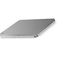
TMC2192KHC Fairchild Semiconductor, TMC2192KHC Datasheet - Page 32

TMC2192KHC
Manufacturer Part Number
TMC2192KHC
Description
Video ICs
Manufacturer
Fairchild Semiconductor
Type
Encoderr
Datasheet
1.TMC2192KHC.pdf
(69 pages)
Specifications of TMC2192KHC
Operating Supply Voltage
- 0.5 V to + 7 V
Supply Current
375 mA
Maximum Operating Temperature
70 C
Package / Case
MQFP-100
Minimum Operating Temperature
0 C
Mounting Style
SMD/SMT
Lead Free Status / RoHS Status
Lead free / RoHS Compliant
Available stocks
Company
Part Number
Manufacturer
Quantity
Price
Company:
Part Number:
TMC2192KHC
Manufacturer:
PHI
Quantity:
90
Part Number:
TMC2192KHC
Manufacturer:
FAIRCHILD/仙童
Quantity:
20 000
TMC2192
sequence simply do not acknowledge (NOACK) the last byte
received and the TMC2192 will terminate the sequence.
A repeated start signal occurs when the master device driv-
ing the serial interface generates a start signal without first
Serial Interface Read/Write Examples
Write to one control register
• Start signal
• Slave Address byte (R/W bit = LOW)
• Block Pointer (00)
• Offset Pointer
• Data byte to base address
• Stop signal
Write to four consecutive control registers
• Start signal
• Slave Address byte (R/W bit = LOW)
• Block Pointer (00)
• Offset Pointer
• Data byte to base address
• Data byte to (base address + 1)
• Data byte to (base address + 2)
• Data byte to (base address + 3)
• Stop signal
Write to one OLUT location
• Start signal
• Slave Address byte (R/W bit = LOW)
• Block Pointer (01)
• Offset Pointer (base address)
• Data byte to base address (Y)
• Data byte to base address (Cb)
• Data byte to base address (Cr)
• Stop signal
32
SDA
SCL
SDA
SCL
Bit 7
A
6
Bit 6
A
5
Figure 26. Serial Interface – Typical Byte Transfer
Figure 27. Serial Interface – Chip Address
Bit 5
A
4
Bit 4
A
3
Bit 3
A
generating a stop signal to terminate the current communica-
tion. This is used to change the mode of communication
(read, write) between the slave and master without releasing
the serial interface lines.
Write to four consecutive OLUT locations
• Start signal
• Slave Address byte (R/W bit = LOW)
• Block Pointer (01)
• Offset Pointer (base address)
• Data byte to base address (Y)
• Data byte to base address (Cb)
• Data byte to base address (Cr)
• Data byte to base address +1 (Y)
• Data byte to base address +1 (Cb)
• Data byte to base address +1 (Cr)
• Data byte to base address +2 (Y)
• Data byte to base address +2 (Cb)
• Data byte to base address +2 (Cr)
• Data byte to base address +3 (Y)
• Data byte to base address +3 (Cb)
• Data byte to base address +3 (Cr)
• Stop signal
Read from one control register
• Start signal
• Slave Address byte (R/W bit = LOW)
• Block Pointer (00)
• Offset Pointer
• Stop signal
• Start signal
• Slave Address byte (R/W bit = HIGH)
• Data byte from base address
• NOACK
2
SA
Bit 2
1
SA
Bit 1
0
R/W
Bit 0
PRODUCT SPECIFICATION
REV. 1.0.0 8/13/03
ACK
ACK
65-6294-30
65-6294-29


