AD9254-150EBZ Analog Devices Inc, AD9254-150EBZ Datasheet - Page 16
AD9254-150EBZ
Manufacturer Part Number
AD9254-150EBZ
Description
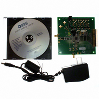
1.8V 14Bit 150 MSPS ADC EB
Manufacturer
Analog Devices Inc
Datasheet
1.AD9254BCPZRL7-150.pdf
(40 pages)
Specifications of AD9254-150EBZ
Number Of Adc's
1
Number Of Bits
14
Sampling Rate (per Second)
150M
Data Interface
Serial
Inputs Per Adc
1 Differential
Input Range
2 Vpp
Power (typ) @ Conditions
506mW @ 150MSPS
Voltage Supply Source
Single Supply
Operating Temperature
-40°C ~ 85°C
Utilized Ic / Part
AD9254
Lead Free Status / RoHS Status
Lead free / RoHS Compliant


AD9254
Table 9. Reference Configuration Summary
Selected Mode
External Reference
Internal Fixed Reference
Programmable Reference
Internal Fixed Reference
VOLTAGE REFERENCE
A stable and accurate voltage reference is built into the AD9254.
The input range is adjustable by varying the reference voltage
applied to the AD9254, using either the internal reference or an
externally applied reference voltage. The input span of the ADC
tracks reference voltage changes linearly. The various reference
modes are summarized in the following sections. The Reference
Decoupling section describes the best practices and require-
ments for PCB layout of the reference.
Internal Reference Connection
A comparator within the AD9254 detects the potential at the
SENSE pin and configures the reference into four possible
states, as summarized in Table 9. If SENSE is grounded, the
reference amplifier switch is connected to the internal resistor
divider (see Figure 37), setting VREF to 1 V.
2V p-p
0.1µF
0.1µF
C
D
0.1µF
R
D
AVDD
SENSE Voltage
VREF
0.2 V to VREF
AGND to 0.2 V
P
A
0Ω
0Ω
R
Figure 36. Differential Input Configuration Using the AD8352
G
16
Figure 35. Differential Double Balun Input Configuration
1
2
3
4
5
S
V
AD8352
S
CC
8, 13
14
0.1µF
0.1µF
10
11
P
Rev. 0 | Page 16 of 40
0.1µF
0.1µF
Resulting VREF (V)
N/A
0.5
1.0
0
0.1µF
0.1µF
5 .
×
25Ω
25Ω
⎛ +
⎜
⎝
1
200Ω
200Ω
R
R
Connecting the SENSE pin to VREF switches the reference
amplifier input to the SENSE pin, completing the loop and
providing a 0.5 V reference output. If a resistor divider is
connected external to the chip, as shown in Figure 38, the
switch sets to the SENSE pin. This puts the reference amplifier
in a noninverting mode with the VREF output defined as
If the SENSE pin is connected to AVDD, the reference amplifier
is disabled, and an external reference voltage can be applied to
the VREF pin (see the External Reference Operation section).
The input range of the ADC always equals twice the voltage at
the reference pin for either an internal or an external reference.
2
1
0.1µF
⎞
⎟
⎠
(see Figure 38)
VREF
0.1µF
R
R
R
R
C
C
=
0
5 .
⎛ +
⎜
⎝
1
VIN+
VIN–
VIN+
VIN–
AD9254
R2
R1
AD9254
⎞
⎟
⎠
CML
CML
Resulting Differential
Span (V p-p)
2 × external reference
1.0
2 × VREF
2.0
Related parts for AD9254-150EBZ
Image
Part Number
Description
Manufacturer
Datasheet
Request
R

Part Number:
Description:
±1.7g Dual-Axis IMEMS Accelerometer Evaluation Board
Manufacturer:
Analog Devices Inc
Datasheet:

Part Number:
Description:
Inertial Sensor Evaluation System
Manufacturer:
Analog Devices Inc
Datasheet:
Part Number:
Description:
Manufacturer:
Analog Devices Inc
Datasheet:
Part Number:
Description:
Manufacturer:
Analog Devices Inc
Datasheet:
Part Number:
Description:
Manufacturer:
Analog Devices Inc
Datasheet:
Part Number:
Description:
Manufacturer:
Analog Devices Inc
Datasheet:
Part Number:
Description:
Manufacturer:
Analog Devices Inc
Datasheet:
Part Number:
Description:
Manufacturer:
Analog Devices Inc
Datasheet:
Part Number:
Description:
Manufacturer:
Analog Devices Inc
Datasheet:
Part Number:
Description:
Manufacturer:
Analog Devices Inc
Datasheet:
Part Number:
Description:
Manufacturer:
Analog Devices Inc
Datasheet:
Part Number:
Description:
Manufacturer:
Analog Devices Inc
Datasheet:
Part Number:
Description:
Manufacturer:
Analog Devices Inc
Datasheet: