MA160014 Microchip Technology, MA160014 Datasheet - Page 59
MA160014
Manufacturer Part Number
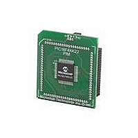
MA160014
Description
MOD PLUG-IN 44PIN PIC18LF45K22
Manufacturer
Microchip Technology
Series
PIC® XLP™ 18Fr
Datasheet
1.PIC18F26J13-ISS.pdf
(496 pages)
Specifications of MA160014
Accessory Type
Plug-In Module (PIM) - PIC18LF45K10
Product
Microcontroller Modules
Data Bus Width
8 bit
Core Processor
PIC18LF45K22
Interface Type
I2C, SPI
Operating Supply Voltage
1.8 V to 5.5 V
Lead Free Status / RoHS Status
Lead free / RoHS Compliant
For Use With/related Products
PICDEM PIC18 Explorer, DM183032
Lead Free Status / Rohs Status
Lead free / RoHS Compliant
Available stocks
Company
Part Number
Manufacturer
Quantity
Price
Company:

Part Number:
MA160014
Manufacturer:
Microchip Technology
Quantity:
135
Company:
Part Number:
MA160014
Manufacturer:
MICROCHIP
Quantity:
12 000


4.0
The PIC18(L)F2X/4XK22 devices differentiate between
various kinds of Reset:
a)
b)
c)
d)
e)
f)
g)
h)
This section discusses Resets generated by MCLR,
POR and BOR and covers the operation of the various
start-up timers. Stack Reset events are covered in
Section 5.1.2.4 “Stack Full and Underflow Resets”.
WDT Resets are covered in
Timer
FIGURE 4-1:
2010 Microchip Technology Inc.
OSC1
MCLR
V
Note 1: See
Power-on Reset (POR)
MCLR Reset during normal operation
MCLR Reset during power-managed modes
Watchdog Timer (WDT) Reset (during
execution)
Programmable Brown-out Reset (BOR)
RESET Instruction
Stack Full Reset
Stack Underflow Reset
DD
(WDT)”.
RESET
2: PWRT and OST counters are reset by POR and BOR. See Sections
LFINTOSC
Instruction
RESET
OST/PWRT
Pointer
32 s
Stack
( )_IDLE
Brown-out
Time-out
Detect
Table 4-2
Sleep
WDT
Reset
V
DD
OST
SIMPLIFIED BLOCK DIAGRAM OF ON-CHIP RESET CIRCUIT
PWRT
Stack Full/Underflow Reset
External Reset
MCLRE
10-bit Ripple Counter
11-bit Ripple Counter
(2)
for time-out situations.
BOREN
Section 24.2 “Watchdog
(2)
POR
1024 Cycles
65.5 ms
Preliminary
A simplified block diagram of the On-Chip Reset Circuit
is shown in
4.1
Device Reset events are tracked through the RCON
register
register indicate that a specific Reset event has
occurred. In most cases, these bits can only be cleared
by the event and must be set by the application after
the event. The state of these flag bits, taken together,
can be read to indicate the type of Reset that just
occurred. This is described in more detail in
Section 4.6 “Reset State of
The RCON register also has control bits for setting
interrupt priority (IPEN) and software control of the
BOR (SBOREN). Interrupt priority is discussed in
Section 9.0
Section 4.4 “Brown-out Reset
PIC18(L)F2X/4XK22
RCON Register
(Register
4.3
Figure
“Interrupts”.
and 4.4.
4-1.
4-1). The lower five bits of the
S
R
Registers”.
BOR
(BOR)”.
DS41412D-page 59
Q
is
Enable OST
Enable PWRT
Chip_Reset
covered
(1)
in
Related parts for MA160014
Image
Part Number
Description
Manufacturer
Datasheet
Request
R

Part Number:
Description:
Manufacturer:
Microchip Technology Inc.
Datasheet:
Part Number:
Description:
Manufacturer:
Microchip Technology Inc.
Datasheet:
Part Number:
Description:
Manufacturer:
Microchip Technology Inc.
Datasheet:
Part Number:
Description:
Manufacturer:
Microchip Technology Inc.
Datasheet:
Part Number:
Description:
Manufacturer:
Microchip Technology Inc.
Datasheet:
Part Number:
Description:
Manufacturer:
Microchip Technology Inc.
Datasheet:
Part Number:
Description:
Manufacturer:
Microchip Technology Inc.
Datasheet:
Part Number:
Description:
Manufacturer:
Microchip Technology Inc.
Datasheet: