MA160014 Microchip Technology, MA160014 Datasheet - Page 213
MA160014
Manufacturer Part Number
MA160014
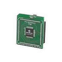
Description
MOD PLUG-IN 44PIN PIC18LF45K22
Manufacturer
Microchip Technology
Series
PIC® XLP™ 18Fr
Datasheet
1.PIC18F26J13-ISS.pdf
(496 pages)
Specifications of MA160014
Accessory Type
Plug-In Module (PIM) - PIC18LF45K10
Product
Microcontroller Modules
Data Bus Width
8 bit
Core Processor
PIC18LF45K22
Interface Type
I2C, SPI
Operating Supply Voltage
1.8 V to 5.5 V
Lead Free Status / RoHS Status
Lead free / RoHS Compliant
For Use With/related Products
PICDEM PIC18 Explorer, DM183032
Lead Free Status / Rohs Status
Lead free / RoHS Compliant
Available stocks
Company
Part Number
Manufacturer
Quantity
Price
Company:

Part Number:
MA160014
Manufacturer:
Microchip Technology
Quantity:
135
Company:
Part Number:
MA160014
Manufacturer:
MICROCHIP
Quantity:
12 000


15.2.3
The master can initiate the data transfer at any time
because it controls the SCKx line. The master
determines when the slave (Processor 2,
is to broadcast data by the software protocol.
In Master mode, the data is transmitted/received as
soon as the SSPxBUF register is written to. If the SPI
is only going to receive, the SDOx output could be dis-
abled (programmed as an input). The SSPxSR register
will continue to shift in the signal present on the SDIx
pin at the programmed clock rate. As each byte is
received, it will be loaded into the SSPxBUF register as
if a normal received byte (interrupts and Status bits
appropriately set).
FIGURE 15-6:
2010 Microchip Technology Inc.
Write to
SSPxBUF
SCKx
(CKP = 0
CKE = 0)
SCKx
(CKP = 1
CKE = 0)
SCKx
(CKP = 0
CKE = 1)
SCKx
(CKP = 1
CKE = 1)
SDOx
(CKE = 0)
SDOx
(CKE = 1)
SDIx
(SMP = 0)
Input
Sample
(SMP = 0)
SDIx
(SMP = 1)
Input
Sample
(SMP = 1)
SSPxIF
SSPxSR to
SSPxBUF
SPI MASTER MODE
SPI MODE WAVEFORM (MASTER MODE)
bit 7
bit 7
bit 7
bit 7
bit 6
bit 6
Figure
bit 5
bit 5
15-5)
Preliminary
bit 4
bit 4
bit 3
bit 3
The clock polarity is selected by appropriately
programming the CKP bit of the SSPxCON1 register
and the CKE bit of the SSPxSTAT register. This then,
would give waveforms for SPI communication as
shown in
where the MSB is transmitted first. In Master mode, the
SPI clock rate (bit rate) is user programmable to be one
of the following:
• F
• F
• F
• Timer2 output/2
• F
Figure 15-6
When the CKE bit is set, the SDOx data is valid before
there is a clock edge on SCKx. The change of the input
sample is shown based on the state of the SMP bit. The
time when the SSPxBUF is loaded with the received
data is shown.
PIC18(L)F2X/4XK22
OSC
OSC
OSC
OSC
/4 (or T
/16 (or 4 * T
/64 (or 16 * T
/(4 * (SSPxADD + 1))
bit 2
bit 2
Figure
shows the waveforms for Master mode.
CY
)
bit 1
bit 1
15-6,
CY
CY
)
)
Figure 15-8
bit 0
bit 0
bit 0
bit 0
DS41412D-page 213
and
4 Clock
Modes
Figure
15-9,
Related parts for MA160014
Image
Part Number
Description
Manufacturer
Datasheet
Request
R

Part Number:
Description:
Manufacturer:
Microchip Technology Inc.
Datasheet:
Part Number:
Description:
Manufacturer:
Microchip Technology Inc.
Datasheet:
Part Number:
Description:
Manufacturer:
Microchip Technology Inc.
Datasheet:
Part Number:
Description:
Manufacturer:
Microchip Technology Inc.
Datasheet:
Part Number:
Description:
Manufacturer:
Microchip Technology Inc.
Datasheet:
Part Number:
Description:
Manufacturer:
Microchip Technology Inc.
Datasheet:
Part Number:
Description:
Manufacturer:
Microchip Technology Inc.
Datasheet:
Part Number:
Description:
Manufacturer:
Microchip Technology Inc.
Datasheet: