MA160014 Microchip Technology, MA160014 Datasheet - Page 197
MA160014
Manufacturer Part Number
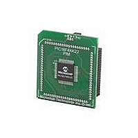
MA160014
Description
MOD PLUG-IN 44PIN PIC18LF45K22
Manufacturer
Microchip Technology
Series
PIC® XLP™ 18Fr
Datasheet
1.PIC18F26J13-ISS.pdf
(496 pages)
Specifications of MA160014
Accessory Type
Plug-In Module (PIM) - PIC18LF45K10
Product
Microcontroller Modules
Data Bus Width
8 bit
Core Processor
PIC18LF45K22
Interface Type
I2C, SPI
Operating Supply Voltage
1.8 V to 5.5 V
Lead Free Status / RoHS Status
Lead free / RoHS Compliant
For Use With/related Products
PICDEM PIC18 Explorer, DM183032
Lead Free Status / Rohs Status
Lead free / RoHS Compliant
Available stocks
Company
Part Number
Manufacturer
Quantity
Price
Company:

Part Number:
MA160014
Manufacturer:
Microchip Technology
Quantity:
135
Company:
Part Number:
MA160014
Manufacturer:
MICROCHIP
Quantity:
12 000


14.4.5
In Half-Bridge applications where all power switches
are modulated at the PWM frequency, the power
switches normally require more time to turn off than to
turn on. If both the upper and lower power switches are
switched at the same time (one turned on, and the
other turned off), both switches may be on for a short
period of time until one switch completely turns off.
During this brief interval, a very high current (shoot-
through current) will flow through both power switches,
shorting the bridge supply. To avoid this potentially
destructive shoot-through current from flowing during
switching, turning on either of the power switches is
normally delayed to allow the other switch to
completely turn off.
In Half-Bridge mode, a digitally programmable dead-
band delay is available to avoid shoot-through current
from destroying the bridge power switches. The delay
occurs at the signal transition from the non-active state
to the active state. See
The lower seven bits of the associated PWMxCON
register
of microcontroller instruction cycles (T
FIGURE 14-17:
2010 Microchip Technology Inc.
Standard Half-Bridge Circuit (“Push-Pull”)
(Register
PROGRAMMABLE DEAD-BAND
DELAY MODE
14-6) sets the delay period in terms
EXAMPLE OF HALF-BRIDGE APPLICATIONS
Figure 14-16
CY
for illustration.
or 4 T
PxA
PxB
OSC
).
Preliminary
FET
Driver
FET
Driver
FIGURE 14-16:
PxA
PxB
td = Dead-Band Delay
PIC18(L)F2X/4XK22
Note 1: At this time, the TMRx register is equal to the
(2)
(2)
V+
V-
2: Output signals are shown as active-high.
(1)
td
Pulse Width
PRx register.
Load
Period
td
EXAMPLE OF HALF-
BRIDGE PWM OUTPUT
+
V
-
+
V
-
(1)
DS41412D-page 197
Period
(1)
Related parts for MA160014
Image
Part Number
Description
Manufacturer
Datasheet
Request
R

Part Number:
Description:
Manufacturer:
Microchip Technology Inc.
Datasheet:
Part Number:
Description:
Manufacturer:
Microchip Technology Inc.
Datasheet:
Part Number:
Description:
Manufacturer:
Microchip Technology Inc.
Datasheet:
Part Number:
Description:
Manufacturer:
Microchip Technology Inc.
Datasheet:
Part Number:
Description:
Manufacturer:
Microchip Technology Inc.
Datasheet:
Part Number:
Description:
Manufacturer:
Microchip Technology Inc.
Datasheet:
Part Number:
Description:
Manufacturer:
Microchip Technology Inc.
Datasheet:
Part Number:
Description:
Manufacturer:
Microchip Technology Inc.
Datasheet: