MA160014 Microchip Technology, MA160014 Datasheet - Page 483
MA160014
Manufacturer Part Number
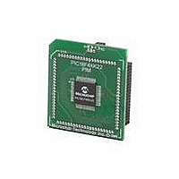
MA160014
Description
MOD PLUG-IN 44PIN PIC18LF45K22
Manufacturer
Microchip Technology
Series
PIC® XLP™ 18Fr
Datasheet
1.PIC18F26J13-ISS.pdf
(496 pages)
Specifications of MA160014
Accessory Type
Plug-In Module (PIM) - PIC18LF45K10
Product
Microcontroller Modules
Data Bus Width
8 bit
Core Processor
PIC18LF45K22
Interface Type
I2C, SPI
Operating Supply Voltage
1.8 V to 5.5 V
Lead Free Status / RoHS Status
Lead free / RoHS Compliant
For Use With/related Products
PICDEM PIC18 Explorer, DM183032
Lead Free Status / Rohs Status
Lead free / RoHS Compliant
Available stocks
Company
Part Number
Manufacturer
Quantity
Price
Company:

Part Number:
MA160014
Manufacturer:
Microchip Technology
Quantity:
135
Company:
Part Number:
MA160014
Manufacturer:
MICROCHIP
Quantity:
12 000


INDEX
A
A/D
Absolute Maximum Ratings ............................................. 421
AC (Timing) Characteristics ............................................. 441
AC Characteristics
Access Bank
ACKSTAT ........................................................................ 242
ACKSTAT Status Flag ..................................................... 242
ADC ................................................................................. 291
ADCON0 Register ............................................................ 298
ADCON1 Register ............................................................ 299
ADCON2 Register ............................................................ 300
ADDFSR .......................................................................... 410
ADDLW ............................................................................ 373
ADDULNK ........................................................................ 410
ADDWF ............................................................................ 373
ADDWFC ......................................................................... 374
ADRESH Register (ADFM = 0) ........................................ 301
ADRESH Register (ADFM = 1) ........................................ 301
ADRESL Register (ADFM = 0) ......................................... 301
ADRESL Register (ADFM = 1) ......................................... 301
Analog Input Connection Considerations ......................... 312
Analog-to-Digital Converter. See ADC
ANDLW ............................................................................ 374
ANDWF ............................................................................ 375
Assembler
B
Bank Select Register (BSR) ............................................... 76
BAUDCON Register ......................................................... 274
BC .................................................................................... 375
BCF .................................................................................. 376
2010 Microchip Technology Inc.
Analog Port Pins, Configuring .................................. 304
Associated Registers ............................................... 304
Conversions ............................................................. 295
Converter Characteristics ........................................ 458
Discharge ................................................................. 296
Selecting and Configuring Acquisition Time ............ 292
Load Conditions for Device Timing Specifications ... 442
Parameter Symbology ............................................. 441
Temperature and Voltage Specifications ................. 442
Timing Conditions .................................................... 442
Internal RC Accuracy ............................................... 444
Mapping with Indexed Literal Offset Mode ................. 94
Acquisition Requirements ........................................ 302
Block Diagram .......................................................... 291
Calculating Acquisition Time .................................... 302
Channel Selection .................................................... 292
Configuration ............................................................ 292
Conversion Clock ..................................................... 293
Conversion Procedure ............................................. 297
Internal Sampling Switch (R
Interrupts .................................................................. 293
Operation ................................................................. 295
Operation During Sleep ........................................... 296
Port Configuration .................................................... 292
Power Management ................................................. 296
Reference Voltage (V
Result Formatting ..................................................... 294
Source Impedance ................................................... 302
Special Event Trigger ............................................... 296
Starting an A/D Conversion ..................................... 294
MPASM Assembler .................................................. 418
REF
) ........................................ 292
SS
) I
MPEDANCE
............. 302
Preliminary
BF ............................................................................ 242, 244
BF Status Flag ......................................................... 242, 244
Block Diagrams
BN .................................................................................... 376
BNC ................................................................................. 377
BNN ................................................................................. 377
BNOV .............................................................................. 378
BNZ ................................................................................. 378
BOR. See Brown-out Reset.
BOV ................................................................................. 381
BRA ................................................................................. 379
Break Character (12-bit) Transmit and Receive .............. 282
Brown-out Reset (BOR) ..................................................... 62
BSF .................................................................................. 379
BTFSC ............................................................................. 380
BTFSS ............................................................................. 380
BTG ................................................................................. 381
BZ .................................................................................... 382
C
C Compilers
PIC18(L)F2X/4XK22
(CCP) Capture Mode Operation .............................. 178
ADC ......................................................................... 291
ADC Transfer Function ............................................ 303
Analog Input Model .......................................... 303, 312
CCP PWM ............................................................... 184
Comparator 1 ........................................................... 306
Compare .................................................................. 181
Crystal Operation ....................................................... 35
CTMU ...................................................................... 317
CTMU Current Source Calibration Circuit ............... 320
CTMU Typical Connections and Internal Configuration
CTMU Typical Connections and Internal Configuration
Digital-to-Analog Converter (DAC) .......................... 340
EUSART Receive .................................................... 264
EUSART Transmit ................................................... 263
External POR Circuit (Slow V
External RC Mode ..................................................... 36
Fail-Safe Clock Monitor (FSCM) ................................ 44
Generic I/O Port ....................................................... 133
High/Low-Voltage Detect with External Input .......... 344
Interrupt Logic .......................................................... 114
On-Chip Reset Circuit ................................................ 59
PIC18F46K22 ............................................................ 16
PWM (Enhanced) .................................................... 188
Reads from Flash Program Memory ......................... 99
Resonator Operation ................................................. 35
Table Read Operation ............................................... 95
Table Write Operation ............................................... 96
Table Writes to Flash Program Memory .................. 101
Timer0 in 16-Bit Mode ............................................. 159
Timer0 in 8-Bit Mode ............................................... 158
Timer1 ..................................................................... 161
Timer1 Gate ............................................. 167, 168, 169
Timer2/4/6 ............................................................... 173
Voltage Reference ................................................... 337
Voltage Reference Output Buffer Example ............. 340
Watchdog Timer ...................................................... 360
Detecting ................................................................... 62
Disabling in Sleep Mode ............................................ 62
Minimum Enable Time ............................................... 62
Software Enabled ...................................................... 62
for Pulse Delay Generation ............................. 328
for Time Measurement .................................... 327
DD
Power-up) .............. 61
DS41412D-page 483
Related parts for MA160014
Image
Part Number
Description
Manufacturer
Datasheet
Request
R

Part Number:
Description:
Manufacturer:
Microchip Technology Inc.
Datasheet:
Part Number:
Description:
Manufacturer:
Microchip Technology Inc.
Datasheet:
Part Number:
Description:
Manufacturer:
Microchip Technology Inc.
Datasheet:
Part Number:
Description:
Manufacturer:
Microchip Technology Inc.
Datasheet:
Part Number:
Description:
Manufacturer:
Microchip Technology Inc.
Datasheet:
Part Number:
Description:
Manufacturer:
Microchip Technology Inc.
Datasheet:
Part Number:
Description:
Manufacturer:
Microchip Technology Inc.
Datasheet:
Part Number:
Description:
Manufacturer:
Microchip Technology Inc.
Datasheet: