33000 Parallax Inc, 33000 Datasheet - Page 11
33000
Manufacturer Part Number
33000
Description
Power Management Modules & Development Tools 30W Solar Cell Kit
Manufacturer
Parallax Inc
Datasheet
1.33000.pdf
(20 pages)
Specifications of 33000
New! Us2012 Catalog Page
Solar Cells_Panels
Voltage - Output
*
Operating Temperature
*
Current Short Circuit (isc)
*
Package / Case
-
Lead Free Status / RoHS Status
Lead free / RoHS Compliant
Available stocks
Company
Part Number
Manufacturer
Quantity
Price
Company:

Part Number:
33000-0001
Manufacturer:
MOLEX
Quantity:
43 635
Company:
Part Number:
33000-0001
Manufacturer:
MOLEX
Quantity:
35 000
Company:
Part Number:
33000-0002
Manufacturer:
MOLEX
Quantity:
25 000
Company:
Part Number:
33000-0002
Manufacturer:
STARCONN
Quantity:
12 450
Company:
Part Number:
33000-0003
Manufacturer:
MOLEX
Quantity:
43 637
Part Number:
330000001
Manufacturer:
MOLEX
Quantity:
20 000
Part Number:
330000002
Manufacturer:
MOLEX
Quantity:
20 000


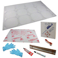
Step 8 — Preparing cells for Base Panel cavities 1, 5, and 9 (refer to Figure 2)
Section C – Cell Installation and Final Assembly
Step 9 — Installing the cells into the base panel
As you begin to install the cells into the Base Panel, it is very important to remember that the Panel is
slightly bowed and quite flexible (because of the machining operation), and the cells are not. Therefore,
if you must lift the Panel up from your work surface, be sure to support it in the center, so as to not allow
it to sag and possibly break some cells.
The drops of glue that will hold each cell in its cavity should be in line with the conductive strips of the
solar cell. It is important to note that the cell should sit flat in the cavity. If you allow the glue to
harden before placing the cell, scrape the glue off and do it again. With a low temperature hot glue gun,
you have about 10 seconds or so to place the cell, so don’t rush it – but don’t delay either.
Copyright © Parallax Inc.
Cut (6) tabbing wires, 5.25”
long.
Following the same flux and
soldering procedures in Step 7,
place the tabbing wire so that it
extends past the edge of the cell
1/2”, as shown in Figure 21.
Prepare two more cells like this
one for a total of three.
Temporarily place one of the 10”
long tabbed cells into cavity #4,
and gently push down with two
fingers, as shown in Figure 22.
Look across the top of the Base
Panel from a very low angle to
see if the cell, when gently
pressed flat to the cavity, is fully
recessed. If it is not, check for
solder blobs or spikes on the
bottom tabbing wires and reflow
any joints as necessary.
30 Watt Solar Panel Kit (#33000)
Figure 21
Figure 22
v1.0 2/19/2010 Page 11 of 20
Related parts for 33000
Image
Part Number
Description
Manufacturer
Datasheet
Request
R


Part Number:
Description:
Microcontroller Modules & Accessories DISCONTINUED BY PARALLAX
Manufacturer:
Parallax Inc

Part Number:
Description:
BOOK UNDERSTANDING SIGNALS
Manufacturer:
Parallax Inc
Datasheet:


Part Number:
Description:
COMPETITION RING FOR SUMOBOT
Manufacturer:
Parallax Inc
Datasheet:


Part Number:
Description:
TEXT INFRARED REMOTE FOR BOE-BOT
Manufacturer:
Parallax Inc
Datasheet:
Part Number:
Description:
BOARD EXPERIMENT+LCD NX-1000
Manufacturer:
Parallax Inc
Datasheet:

Part Number:
Description:
CONTROLLER 16SERVO MOTOR CONTROL
Manufacturer:
Parallax Inc
Datasheet:

Part Number:
Description:
BASIC STAMP LOGIC ANALYZER
Manufacturer:
Parallax Inc
Datasheet:

Part Number:
Description:
IC MCU 2K FLASH 50MHZ SO-18
Manufacturer:
Parallax Inc
Datasheet: