33000 Parallax Inc, 33000 Datasheet
33000
Specifications of 33000
Available stocks


Related parts for 33000


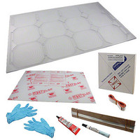
33000 Summary of contents
Page 1
... Application Ideas Portable power for remote monitoring & control systems Fixed power station for energy production Mobile robotics and solar charging stations 30 Watt Solar Panel Kit (#33000) Office: (916) 624-8333 Fax: (916) 624-8003 Sales: (888) 512-1024 Tech Support: (888) 997-8267 v1.0 2/19/2010 Page ...
Page 2
... WATCH THE VIDEOS demonstrating safe cell handling and soldering techniques before beginning. Search “33000” at www.parallax.com, and then find the video link on the 33000 product page. (You may also download the latest version of this documentation as a full-color PDF from the same page.) ...
Page 3
... The white strip covers the bare (non-adhesive) copper conductors and the pink strip covers the sticky side. Copyright © Parallax Inc. Figure 2 Figure 3 30 Watt Solar Panel Kit (#33000) v1.0 2/19/2010 Page ...
Page 4
... Copyright © Parallax Inc. Figure 4 Figure 5 Figure 6 30 Watt Solar Panel Kit (#33000) v1.0 2/19/2010 Page ...
Page 5
... Cut a single bus-bar 3.5” long, and place it into groove “C,” and remove the white protective cover. Your panel should now look like that shown in Figure 9. Copyright © Parallax Inc. Figure 9 30 Watt Solar Panel Kit (#33000) Figure 7 Figure 8 v1.0 2/19/2010 Page ...
Page 6
... This checks the continuity of the solder connections between each of the solder bridges to bus-bar “F.” All (5) measurements should be zero (or near zero) ohms. If not, then re- flow your solder connections to make it so. Copyright © Parallax Inc. Figure 10 Figure 11 30 Watt Solar Panel Kit (#33000) v1.0 2/19/2010 Page ...
Page 7
... WATCH THE VIDEO demonstrating safe cell handling and soldering techniques before beginning. Search “33000” at www.parallax.com, and then find the video link on the 33000 product page. If you break a cell in any of the following steps, don’t panic page 19 and read through Section F – ...
Page 8
... This is normal. If the cell is incorrectly restrained by the tape, stress will build up and the cell may break, especially when you try to remove the tape. Copyright © Parallax Inc. Proper tape location to hold the cell for tabbing wire installation Figure 15 30 Watt Solar Panel Kit (#33000) Figure 14 v1.0 2/19/2010 Page ...
Page 9
... Next, apply a coat of flux to the top of the tabbing wire itself, as shown in Figure 18. Make sure that the flux is flowing well. Re-prime the flux pen by depressing the tip as necessary. Copyright © Parallax Inc. 30 Watt Solar Panel Kit (#33000) Figure 16 Figure 17 Figure 18 v1.0 2/19/2010 Page ...
Page 10
... Do not handle or flex the cell any more than you have to, until final assembly in Section C below. Repeat this tabbing wire procedure for eight more cells (for a total of nine). Copyright © Parallax Inc. crack 30 Watt Solar Panel Kit (#33000) a cell but it’s still all in one piece, Figure 19 Figure 20 v1.0 2/19/2010 Page ...
Page 11
... With a low temperature hot glue gun, you have about 10 seconds place the cell, so don’t rush it – but don’t delay either. Copyright © Parallax Inc. Figure 21 Figure 22 30 Watt Solar Panel Kit (#33000) v1.0 2/19/2010 Page ...
Page 12
... See Figure 25. Be careful to not stress the cell as you bend the wires gently upward. Copyright © Parallax Inc. Figure 23 Figure 24 Figure 25 30 Watt Solar Panel Kit (#33000) v1.0 2/19/2010 Page ...
Page 13
... Finish the first row of cells by soldering the tabbing wires from the cell in cavity #1 to the bus-bar in groove “C” as shown in Figure 28. Copyright © Parallax Inc. sees, 30 Watt Solar Panel Kit (#33000) Figure 26 Figure 27 Figure 28 v1.0 2/19/2010 Page ...
Page 14
... Don’t forget to use flux across not only the top of the cells, but also the top of the tabbing wires. Your panel should now look like Figure 30. Copyright © Parallax Inc. Figure 29 Figure 30 30 Watt Solar Panel Kit (#33000) v1.0 2/19/2010 Page ...
Page 15
... Cut two pieces of tabbing wire 5.75” long and solder them to the bus-bar in groove “D.” Then finish the cell installations by making all final solder connections, as shown in Figure 32. Copyright © Parallax Inc. Figure 31 Figure 32 30 Watt Solar Panel Kit (#33000) v1.0 2/19/2010 Page ...
Page 16
... Double-check the solder connections between the bus-bar in groove “C” and the double bus-bar in groove “A.” Double-check the solder joint going from the double bus-bar to the single bar in groove “F”. Copyright © Parallax Inc. Figure 33 30 Watt Solar Panel Kit (#33000) v1.0 2/19/2010 Page ...
Page 17
... A little bit of obscurity is ok, just don’t flood it. Copyright © Parallax Inc. Figure 34 30 Watt Solar Panel Kit (#33000) Be sure to follow all v1.0 2/19/2010 Page ...
Page 18
... That’s it...Congratulations! You now have your own Solar Electric Power Plant! Copyright © Parallax Inc. swiftly carefully! but Cement Cement Figure 35 30 Watt Solar Panel Kit (#33000) Cement v1.0 2/19/2010 Page ...
Page 19
... Place the cell into its cavity. The top tabbing wire from the adjacent cell) can be soldered in place, just like the “normal” procedure. Copyright © Parallax Inc. Not to (#750- 30 Watt Solar Panel Kit (#33000) Figure 36 Figure 37 v1.0 2/19/2010 Page ...
Page 20
... Copyright © Parallax Inc. 30 Watt Solar Panel Kit (#33000) v1.0 2/19/2010 Page ...