NCP5393MNR2G ON Semiconductor, NCP5393MNR2G Datasheet - Page 9
NCP5393MNR2G
Manufacturer Part Number
NCP5393MNR2G
Description
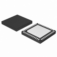
IC CTLR 2/3/4PHASE CPU 48-QFN
Manufacturer
ON Semiconductor
Datasheet
1.NCP5393MNR2G.pdf
(23 pages)
Specifications of NCP5393MNR2G
Applications
Multiphase Controller
Current - Supply
25mA
Voltage - Supply
4.75 V ~ 5.25 V
Operating Temperature
0°C ~ 70°C
Mounting Type
Surface Mount
Package / Case
48-TQFN Exposed Pad
Mounting Style
SMD/SMT
Lead Free Status / RoHS Status
Lead free / RoHS Compliant
Available stocks
Company
Part Number
Manufacturer
Quantity
Price
Company:

Part Number:
NCP5393MNR2G
Manufacturer:
RFMD
Quantity:
10 000
Part Number:
NCP5393MNR2G
Manufacturer:
ON
Quantity:
20 000


ELECTRICAL CHARACTERISTICS
CURRENT SENSE AMPLIFIERS (V
INTERNAL OFFSET VOLTAGE
DRVON & NB_DRVON
V
V
PWM COMPARATORS (V
PWRGOOD OUTPUT
3. Guaranteed by design. Not production tested.
Input Bias Current
Common Mode Input Voltage Range
Differential Mode Input Voltage
Range (Note 3)
Input Offset Voltage (Note 3)
Gain from Current Sense Input to
PWM Comparator
Voltage at Error Amplifier Non-In‐
verting Inputs
Output Voltage (High)
Output Voltage (Low)
Delay Time
Active Internal Pull-up Resistance
Active Internal Pull-down Resistance
Rise Time
Fall Time
Switching Frequency Range
Switching Frequency Accuracy
2- or 4-phase
Switching Frequency Accuracy
3-phase
ROSC Output Voltage
Switching Frequency
Minimum Pulse Width (Note 3)
Propagation Delay (Note 3)
Magnitude of the PWM Ramp
0% Duty Cycle
100% Duty Cycle
PWM Phase Angle Error
PWRGOOD Output Voltage (Low)
PWRGOOD Rise Time
PWRGOOD High-State Leakage
DD
DDNB
PWM OSCILLATOR
PWM OSCILLATOR
Parameter
DD
& V
DDNB
DD
)
& V
CSx = CSxN = 1.4 V
CSx = CSxN = 1.00 V
0 mV < (CSx - CSxN) < 60 mV
Sourcing 500 mA
Sinking 500 mA
Propagation Delays
Sourcing 500 mA
Sinking 500 mA
C
C
ROSC = 49.9 kW
ROSC = 24.9 kW
ROSC = 10 kW
ROSC = 49.9 kW
ROSC = 24.9 kW
ROSC = 10 kW
10 mA ≤ IROSC ≤ 200 mA
F
$20 mV of Overdrive
COMP Voltage at which the PWM Outputs Remain
LOW
COMP Voltage at which the PWM Outputs Remain
HIGH
Between Adjacent Phases
I
External Pullup of 1 kW to 5 V C
= 10% to 90%
V
PGD
(Unless otherwise stated: 0°CvT
SW
PWRGOOD
L
L
DDNB
(PCB) = 20 pF, DV
(PCB) = 20 pF, DV
= 800 kHz
= 5 mA
)
= 5.25 V
http://onsemi.com
Test Conditions
NCP5393
OUT
OUT
9
= 10% to 90%
= 10% to 90%
A
TOTAL
v70°C; 4.75 VvV
= 45 pF, DV
OUT
CC
v5.25 V; All DAC Codes; C
-120
-0.3
-1.0
1.94
Min
-50
100
196
380
803
196
380
803
-15
5.0
3.0
-
-
-
-
-
-
-
-
-
-
-
-
-
-
-
-
1.25
Typ
150
130
125
6.0
1.3
2.0
2.0
1.0
0.2
1.2
10
15
30
10
-
-
-
-
-
-
-
-
-
-
-
-
-
-
-
Max
2.06
VCC
120
900
226
420
981
226
420
981
+15
2.6
1.0
7.0
0.7
0.4
50
-
-
-
-
-
-
-
-
-
-
-
-
-
-
1
= 0.1 mF)
x f
Unit
kHz
kHz
kHz
V/V
mV
mV
nA
kW
mA
ns
ns
ns
ns
ns
ns
W
V
V
V
V
V
VDD
V
V
V
V
°
Related parts for NCP5393MNR2G
Image
Part Number
Description
Manufacturer
Datasheet
Request
R

Part Number:
Description:
2/3/4-Phase Controller
Manufacturer:
ON Semiconductor
Datasheet:
Part Number:
Description:
ON Semiconductor [VOLTAGE REGULATOR]
Manufacturer:
ON Semiconductor
Datasheet:
Part Number:
Description:
357-036-542-201 CARDEDGE 36POS DL .156 BLK LOPRO
Manufacturer:
ON Semiconductor
Datasheet:
Part Number:
Description:
357-036-542-201 CARDEDGE 36POS DL .156 BLK LOPRO
Manufacturer:
ON Semiconductor
Datasheet:
Part Number:
Description:
357-036-542-201 CARDEDGE 36POS DL .156 BLK LOPRO
Manufacturer:
ON Semiconductor
Datasheet:
Part Number:
Description:
357-036-542-201 CARDEDGE 36POS DL .156 BLK LOPRO
Manufacturer:
ON Semiconductor
Datasheet:
Part Number:
Description:
357-036-542-201 CARDEDGE 36POS DL .156 BLK LOPRO
Manufacturer:
ON Semiconductor
Datasheet:
Part Number:
Description:
357-036-542-201 CARDEDGE 36POS DL .156 BLK LOPRO
Manufacturer:
ON Semiconductor
Datasheet:
Part Number:
Description:
357-036-542-201 CARDEDGE 36POS DL .156 BLK LOPRO
Manufacturer:
ON Semiconductor
Datasheet:
Part Number:
Description:
357-036-542-201 CARDEDGE 36POS DL .156 BLK LOPRO
Manufacturer:
ON Semiconductor
Datasheet:
Part Number:
Description:
357-036-542-201 CARDEDGE 36POS DL .156 BLK LOPRO
Manufacturer:
ON Semiconductor
Datasheet:
Part Number:
Description:
357-036-542-201 CARDEDGE 36POS DL .156 BLK LOPRO
Manufacturer:
ON Semiconductor
Datasheet:
Part Number:
Description:
Manufacturer:
ON Semiconductor
Datasheet:
Part Number:
Description:
Manufacturer:
ON Semiconductor
Datasheet: