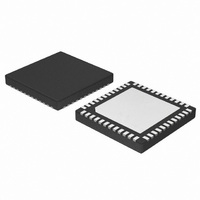
NCP5393MNR2G ON Semiconductor, NCP5393MNR2G Datasheet - Page 20

NCP5393MNR2G
Manufacturer Part Number
NCP5393MNR2G
Description
IC CTLR 2/3/4PHASE CPU 48-QFN
Manufacturer
ON Semiconductor
Datasheet
1.NCP5393MNR2G.pdf
(23 pages)
Specifications of NCP5393MNR2G
Applications
Multiphase Controller
Current - Supply
25mA
Voltage - Supply
4.75 V ~ 5.25 V
Operating Temperature
0°C ~ 70°C
Mounting Type
Surface Mount
Package / Case
48-TQFN Exposed Pad
Mounting Style
SMD/SMT
Lead Free Status / RoHS Status
Lead free / RoHS Compliant
Available stocks
Company
Part Number
Manufacturer
Quantity
Price
Company:
Part Number:
NCP5393MNR2G
Manufacturer:
RFMD
Quantity:
10 000
Part Number:
NCP5393MNR2G
Manufacturer:
ON
Quantity:
20 000
Programming the Current Limit and the Oscillator Frequency
approximately 330 kHz. The ROSC pin provides a 2.0 V
reference voltage which is divided down with a resistor
divider and fed into the current limit pin ILIM. Calculate the
total series resistance to set the frequency and then calculate
the individual RLIM1 and RLIM2 values for the divider.
the ILIM pin to ground. This current is internally mirrored
into a capacitor to create an oscillator. The period is
current of all phases multiplied by a gain of 6. DCR sensed
inductor current is function of the winding temperature. The
best approach is to set the maximum current limit based on
Calculate the current limit voltage:
Solve for the individual resistors:
Final Equation for the Current Limit Threshold
0.75 mW. Selecting the closest available values of 16.9 kW
for RLIM1 and 13.7 kW for RLIM2 yield a nominal
operating frequency of 330 kHz and an approximate current
I LIMIT (T inductor ) ^
The demo board is set for an operating frequency of
The series resistors RLIM1 and RLIM2 sink current from
The current limit function is based on the total sensed
The inductors on the demo board have a DCR at 25°C of
RLIM2 +
V ILIMIT ^ 6 · I MIN_OCP · DCR Tmax )
6 · (DCR 25C · (1 ) 0.00393(T Inductor -25)))
V ILIMIT · R TOTAL
2 · V
RLIM1)RLIM2
2 · V · RLIM2
Figure 12. ROSC vs. Frequency
http://onsemi.com
(eq. 4)
NCP5393
DCR Tmax · Vout
2 · Vin · F sw
20
proportional to the resistance and frequency is inversely
proportional to the total resistance. The total resistance may
be estimated by Equation 2. This equation is valid for the
individual phase frequency in both three and four phase
mode.
the expected average maximum temperature of the inductor
windings.
limit of 152 A at 100°C. The total sensed current can be
observed as a scaled voltage at the VDRP pin added to a
positive, no-load offset of approximately 1.3 V.
*
2 · Vin · F sw
DCR Tmax + DCR 25C ·
Vout
· Vin-Vout
R TOTAL ^ 24686
30.5 · kW ^ 24686
RLIM1 + R TOTAL -R LIM2
L
· Vin-Vout
* (N-1) · Vout
(1 ) 0.00393 (T max -25))
L
* (N-1) · Vout
Fsw -1.1549
330 -1.1549
L
L
(eq. 3)
(eq. 5)
(eq. 6)
(eq. 1)
(eq. 2)


