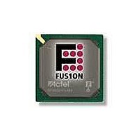
AFS600-PQG208 Actel, AFS600-PQG208 Datasheet - Page 144

AFS600-PQG208
Manufacturer Part Number
AFS600-PQG208
Description
FPGA - Field Programmable Gate Array 600K System Gates
Manufacturer
Actel
Datasheet
1.AFS600-PQG208.pdf
(330 pages)
Specifications of AFS600-PQG208
Processor Series
AFS600
Core
IP Core
Maximum Operating Frequency
1098.9 MHz
Number Of Programmable I/os
95
Data Ram Size
110592
Supply Voltage (max)
1.575 V
Maximum Operating Temperature
+ 70 C
Minimum Operating Temperature
0 C
Development Tools By Supplier
AFS-Eval-Kit, AFS-BRD600, FlashPro 3, FlashPro Lite, Silicon-Explorer II, Silicon-Sculptor 3, SI-EX-TCA
Mounting Style
SMD/SMT
Supply Voltage (min)
1.425 V
Number Of Gates
600 K
Package / Case
PQFP-208
Lead Free Status / RoHS Status
Lead free / RoHS Compliant
Available stocks
Company
Part Number
Manufacturer
Quantity
Price
Company:
Part Number:
AFS600-PQG208
Manufacturer:
Actel
Quantity:
135
Company:
Part Number:
AFS600-PQG208I
Manufacturer:
Microsemi SoC
Quantity:
10 000
- Current page: 144 of 330
- Download datasheet (13Mb)
Device Architecture
Analog Configuration MUX
2- 12 8
The ACM is the interface between the FPGA, the Analog Block configurations, and the real-time counter.
Actel Libero IDE will generate IP that will load and configure the Analog Block via the ACM. However,
users are not limited to using the Libero IDE IP. This section provides a detailed description of the ACM's
register map, truth tables for proper configuration of the Analog Block and RTC, as well as timing
waveforms so users can access and control the ACM directly from their designs.
The Analog Block contains four 8-bit latches per Analog Quad that are initialized through the ACM.
These latches act as configuration bits for Analog Quads. The ACM block runs from the core voltage
supply (1.5 V).
Access to the ACM is achieved via 8-bit address and data busses with enables. The pin list is provided in
Table 2-36 on page
to handle the low-bandwidth requirements of configuring the Analog Block and the RTC (sub-block of the
Analog Block).
Table 2-51
configuration byte for that quad.
Table 2-51 • ACM Address Decode Table for Analog Quad
ACMADDR [7:0] in
Decimal
0
1
2
3
4
5
.
.
.
36
37
38
39
40
41
.
.
.
63
64
65
66
67
68
72
decodes the ACM address space and maps it to the corresponding Analog Quad and
2-82. The ACM clock speed is limited to a maximum of 10 MHz, more than sufficient
MATCHREG0
COUNTER0
COUNTER1
COUNTER2
COUNTER3
COUNTER4
Name
AQ0
AQ0
AQ0
AQ0
AQ1
AQ8
AQ9
AQ9
AQ9
AQ9
–
.
.
.
.
.
.
R e visio n 1
Match register bits 7:0
Counter bits 23:16
Counter bits 31:24
Counter bits 39:32
Counter bits 15:8
Counter bits 7:0
Description
Undefined
Undefined
Undefined
Byte 0
Byte 1
Byte 2
Byte 3
Byte 0
Byte 3
Byte 0
Byte 1
Byte 2
Byte 3
–
.
.
.
Analog Quad
Analog Quad
Analog Quad
Analog Quad
Analog Quad
Analog Quad
Analog Quad
Analog Quad
Analog Quad
Analog Quad
Analog Quad
Analog Quad
Analog Quad
Analog Quad
Associated
Peripheral
RTC
RTC
RTC
RTC
RTC
RTC
RTC
Related parts for AFS600-PQG208
Image
Part Number
Description
Manufacturer
Datasheet
Request
R

Part Number:
Description:
AFS600-1FGG256I
Manufacturer:
Actel
Datasheet:

Part Number:
Description:
AFS600-2FGG256I
Manufacturer:
Actel
Datasheet:


