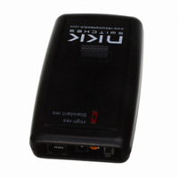
IS-C0203-F-E NKK Switches, IS-C0203-F-E Datasheet - Page 7

IS-C0203-F-E
Manufacturer Part Number
IS-C0203-F-E
Description
SMARTSWITCH CONTROLLER LCD
Manufacturer
NKK Switches
Specifications of IS-C0203-F-E
Accessory Type
Controller
Description/function
SMARTSWITCH Development Kit
For Use With/related Products
SmartSwitch™ Switches
For Use With
360-2345 - SWITCH COMPACT LCD 64X32 RGB360-2343 - SWITCH LCD 64X32 RGB360-2341 - DISPLAY LCD 64X32IS01BCEF - SMARTDISPLAY SUPER YEL/GRN LEDIS01BCE - SMARTDISPLAY SUPER YELLOW LEDIS15SBFP4B - SMARTSWITCH COMPACT WHITE LEDIS15SBCP4EF - SMARTSWITCH COMPACT YEL/GRN LEDIS15SACP4CF - SMARTSWITCH COMPACT RED/GRN LEDIS15ABFP4B - SMARTSWITCH STD BLK W/WHITE LEDIS15ABDP4B - SMARTSWITCH STD BLU W/WHITE LEDIS15ABDP4EG - SMARTSWITCH STD YELLOW/BLUE LEDIS15ABDP4E - SMARTSWITCH STD BLUE W/YEL LEDIS15ABCP4EF - SMARTSWITCH STD YEL/GRN LEDIS15ABCP4E - SMARTSWITCH STD LED YELLOWIS15AACP4CF - SMARTSWITCH STD YEL RED/GRN LED360-2334 - SMARTDISPLAY RED/GREEN/BLUE360-2333 - SMARTDISPLAY SUPER RED/GREEN LED360-2332 - SMARTSWITCH STANDARD RED/GRN/BLU360-2331 - SMARTSWITCH COMPACT RED/GRN/BLU360-2330 - SMARTSWITCH STD RED/GRN LED360-2329 - SMARTSWITCH COMPACT RED/GRN LED
Lead Free Status / RoHS Status
Contains lead / RoHS non-compliant
Other names
360-2425
7850 East Gelding Drive • Scottsdale, AZ 85260-3420
4. Operational Details
Power-Up Sequence (Steps 1,2,3)
Upon power-up or reset, controller performs the following steps:
Step 1: Check the status of Mode Select Switch for mode of operation. Initialize according to selected mode.
Step 2: Check if the flash RAM has been programmed. Compare the check string to flash RAM string.
Step 3: Write all the default initialize values to the flash memory as follows:
Step 4: LED brightness adjustment as follows:
Main Operational Mode
Step 5:
C0203 User Manual.doc
A. If the strings are not the same, the flash RAM is virgin and its data is not acceptable. Step 3 will be
executed. (first time)
B. If the strings are the same, the data from RAM is acceptable. Step 3 is omitted and Step 4 is
executed.
A. Put “BLANK FONT MEMORY” as the picture for location one.
B. Put “BLANK FONT MEMORY” as the picture for location two.
C. Put ONcycle LED’s ON for location #1 and #2.
D. Put OFFcycle LED’s off for location #1 and #2.
E. Put “00H 00H 00H 00H 00H 00H” as attribute for location #1 and #2.
F. Put 00H for software version
G. Write the default setup values such OFFcycle, ON/OFF ratio…
H. Write the virgin check string.
A. Display “DOWN LED” and “UP LED” on the two switches and allow for adjustments of the
B. When the timer expires transmit 83H
C. Initialize and load the data from location 1 and 2 of EEPROM to internal RAM for switch 1 and 2
A. If the switch one is pressed: Transmit 81H to host and execute the attribute.
B. If the switch two is pressed: Transmit 82H to host and execute the attribute.
C. If the timer for switch 1 is expired: Transmit 83H to host and execute the timer attribute.
D. If the timer for switch 2 is expired: Transmit 84H to host and execute the timer attribute.
E. If the switch one is released: Transmit B1H to host.
F. If the switch two is released: Transmit B2H to host.
brightness. There are 8 brightness levels (0 to 7). When the internal timer is expired, the controller
proceeds to Step 5. Every time a switch is pressed, the timer gets reset. If a switch is held
depressed the timer does not run. Switch activity are not reported to host.
respectfully.
(For details see Attribute Execution)
(For details see Attribute Execution)
(For details see Attribute Execution)
(For details see Attribute Execution)
Toll Free 1.877.2BUYNKK (877.228.9655) • Phone 480.991.0942 • Fax 480.998.1435
C0203 Intelligent Controller User Manual
www.nkkswitches.com • Email engineering@nkkswitches.com
Page 7 of 23
0409


