QRE1113 Fairchild Semiconductor, QRE1113 Datasheet - Page 3
QRE1113
Manufacturer Part Number
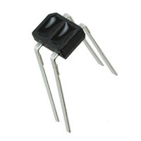
QRE1113
Description
SENSOR REFL 5MM PHOTOTRANS THRU
Manufacturer
Fairchild Semiconductor
Datasheet
1.QRE1113.pdf
(8 pages)
Specifications of QRE1113
Sensing Distance
0.197" (5mm)
Sensing Method
Reflective
Voltage - Collector Emitter Breakdown (max)
30V
Current - Collector (ic) (max)
20mA
Current - Dc Forward (if)
50mA
Output Type
Phototransistor
Response Time
20µs, 20µs
Mounting Type
Through Hole
Package / Case
4-SMD
Operating Temperature
-40°C ~ 85°C
Lead Free Status / RoHS Status
Lead free / RoHS Compliant
Available stocks
Company
Part Number
Manufacturer
Quantity
Price
Company:

Part Number:
QRE1113
Manufacturer:
Fairchild Semiconductor
Quantity:
1 280
Company:
Part Number:
QRE1113
Manufacturer:
SANYO
Quantity:
10 387
Company:
Part Number:
QRE1113GR
Manufacturer:
RENESAS
Quantity:
1 000
Company:
Part Number:
QRE1113GR
Manufacturer:
FSC
Quantity:
57 000
Part Number:
QRE1113GR
Manufacturer:
FAIRCHILD/仙童
Quantity:
20 000


©2002 Fairchild Semiconductor Corporation
QRE1113, QRE1113GR Rev. 1.6.0
Absolute Maximum Ratings
Stresses exceeding the absolute maximum ratings may damage the device. The device may not function or be
operable above the recommended operating conditions and stressing the parts to these levels is not recommended.
In addition, extended exposure to stresses above the recommended operating conditions may affect device reliability.
The absolute maximum ratings are stress ratings only.
Electrical/Optical Characteristics
Notes:
1. Derate power dissipation linearly 1.00mW/°C above 25°C.
2. RMA flux is recommended.
3. Methanol or isopropyl alcohols are recommended as cleaning agents.
4. Soldering iron 1/16" (1.6mm) from housing.
5. Pulse conditions: tp = 100µs; T = 10ms.
6. Measured using an aluminum alloy mirror at d = 1mm.
7. No reflective surface at close proximity.
EMITTER
SENSOR
INPUT DIODE
OUTPUT TRANSISTOR
COUPLED
Symbol
V
CE (SAT)
I
C(ON)
λ
I
V
I
I
CX
PE
t
t
R
D
Symbol
r
f
F
T
T
T
V
V
T
SOL-F
SOL-I
I
OPR
V
P
P
STG
CEO
ECO
I
FP
I
C
F
R
D
D
Parameter
Forward Voltage
Reverse Leakage Current
Peak Emission Wavelength
Collector-Emitter Dark Current
On-State Collector Current
Cross-Talk Collector Current
Saturation Voltage
Rise Time
Fall Time
Parameter
Operating Temperature
Storage Temperature
Soldering Temperature (Iron)
Soldering Temperature (Flow)
Continuous Forward Current
Reverse Voltage
Peak Forward Current
Power Dissipation
Collector-Emitter Voltage
Emitter-Collector Voltage
Collector Current
Power Dissipation
(T
(1)
(1)
A
= 25°C unless otherwise specified)
(5)
I
V
I
I
I
I
V
R
(T
F
F
F
F
F
R
CC
L
A
= 20mA
= 20mA
= 0mA, V
= 20mA, V
= 20mA, V
= 1k Ω
= 5V
= 25°C unless otherwise specified)
Test Conditions
(2,3,4)
= 5V, I
(2,3)
C(ON)
3
CE
CE
CE
= 20V
= 5V
= 5V
= 100µA,
(6)
(7)
260 for 10 sec
240 for 5 sec
Min.
0.10
-40 to +85
-40 to +90
Rating
75
50
50
30
20
5
1
5
Typ.
0.40
940
1.2
20
20
Max.
100
1.6
0.3
10
1
Units
mW
mW
www.fairchildsemi.com
mA
mA
°C
°C
°C
°C
V
A
V
V
Units
mA
nm
µA
nA
µA
µs
V
V
Related parts for QRE1113
Image
Part Number
Description
Manufacturer
Datasheet
Request
R

Part Number:
Description:
Fairchild Semiconductor [IGBT MODULE]
Manufacturer:
Fairchild Semiconductor
Datasheet:

Part Number:
Description:
Discrete Semiconductor Modules
Manufacturer:
Fairchild Semiconductor
Part Number:
Description:
Discrete Semiconductor Modules
Manufacturer:
Fairchild Semiconductor
Part Number:
Description:
This N-Channel MOSFET is produced using Fairchild Semiconductor’s advanced Power Trench® process
Manufacturer:
Fairchild Semiconductor
Datasheet:
Part Number:
Description:
This N-Channel MOSFET is produced using Fairchild Semiconductor’s advanced Power Trench® process
Manufacturer:
Fairchild Semiconductor
Datasheet:
Part Number:
Description:
This N-Channel MOSFET is produced using Fairchild Semiconductor’s advanced PowerTrench® process
Manufacturer:
Fairchild Semiconductor
Datasheet:
Part Number:
Description:
This N-Channel MOSFET is produced using Fairchild Semiconductor’s advanced PowerTrench® process
Manufacturer:
Fairchild Semiconductor
Datasheet:
Part Number:
Description:
This N-Channel MOSFET is produced using Fairchild Semiconductor’s advanced Power Trench® process
Manufacturer:
Fairchild Semiconductor
Datasheet:
Part Number:
Description:
This N-Channel logic Level MOSFETs are produced using Fairchild Semiconductor‘s advanced Power Trench® process that has been special tailored to minimize the on-state resistance and yet maintain superior switching performance
Manufacturer:
Fairchild Semiconductor
Datasheet:
Part Number:
Description:
This N-Channel MOSFET is produced using Fairchild Semiconductor’s advanced Power Trench® process
Manufacturer:
Fairchild Semiconductor
Datasheet:
Part Number:
Description:
This N-Channel SyncFET™ is produced using Fairchild Semiconductor’s advanced PowerTrench® process
Manufacturer:
Fairchild Semiconductor
Datasheet:
Part Number:
Description:
This N-Channel SyncFET™ is produced using Fairchild Semiconductor’s advanced PowerTrench® process
Manufacturer:
Fairchild Semiconductor
Datasheet:
Part Number:
Description:
This N-Channel SyncFET™ is produced using Fairchild Semiconductor’s advanced PowerTrench® process
Manufacturer:
Fairchild Semiconductor
Datasheet:
Part Number:
Description:
This N-Channel logic Level MOSFETs are produced using Fairchild Semiconductor‘s advanced Power Trench® process that has been special tailored to minimize the on-state resistance and yet maintain superior switching performance
Manufacturer:
Fairchild Semiconductor
Datasheet:
Part Number:
Description:
This N-Channel MOSFET is produced using Fairchild Semiconductor’s advanced Power Trench® process that has been especially tailored to minimize the on-state resistance and yet maintain superior switching performance
Manufacturer:
Fairchild Semiconductor
Datasheet: