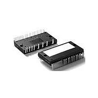
FSAM75SM60A Fairchild Semiconductor, FSAM75SM60A Datasheet - Page 8

FSAM75SM60A
Manufacturer Part Number
FSAM75SM60A
Description
IC SMART PWR MODULE SPM32-CA
Manufacturer
Fairchild Semiconductor
Series
SPM™r
Type
IGBTr
Datasheet
1.FSAM75SM60A.pdf
(16 pages)
Specifications of FSAM75SM60A
Configuration
3 Phase
Current
75A
Voltage
600V
Voltage - Isolation
2500Vrms
Package / Case
SPM32CA
Collector-emitter Saturation Voltage
2.4 V
Gate-emitter Leakage Current
189 W
Power Dissipation
189 W
Mounting Style
SMD/SMT
Operating Temperature (max)
125C
Operating Temperature (min)
-20C
Pin Count
32
Mounting
Through Hole
Case Length
60mm
Case Height
7.2mm
Screening Level
Commercial
Lead Free Status / RoHS Status
Lead free / RoHS Compliant
Available stocks
Company
Part Number
Manufacturer
Quantity
Price
Company:
Part Number:
FSAM75SM60A
Manufacturer:
FSC
Quantity:
120
©2006 Fairchild Semiconductor Corporation
Electrical Characteristics
Control Part
Note:
5. Short-circuit current protection is functioning only at the low-sides. It would be recommended that the value of the external sensing resistor (R
6. The fault-out pulse width t
7. T
Recommended Operating Conditions
Note:
8. SPM might not make response if the PW
Quiescent V
rent
Quiescent V
rent
Fault Output Voltage
Short-Circuit Trip Level
Sensing Voltage
of IGBT Current
Supply Circuit Under-
Voltage Protection
Fault Output Pulse Width
ON Threshold Voltage
OFF Threshold Voltage
ON Threshold Voltage
OFF Threshold Voltage
Resistance of Thermistor
Supply Voltage
Control Supply Voltage
High-side Bias Voltage
Blanking Time for Preventing
Arm-short
PWM Input Signal
Minimum Input Pulse Width
Input ON Threshold Voltage
Input OFF Threshold Voltage
selected around 26 Ω in order to make the SC trip-level of about 100A at the shunt resistors (R
relationship between the external sensing resistor (R
TH
is the temperature of thermistor itself. To know case temperature (T
Item
CC
BS
Item
Supply Cur-
Supply Cur-
FOD
depends on the capacitance value of C
Symbol
V
V
V
UV
UV
V
V
UV
UV
I
I
V
V
V
IN(OFF)
IN(OFF)
QCCH
QCCL
I
SC(ref)
t
IN(ON)
IN(ON)
R
PW
QBS
FOD
FOH
SEN
FOL
IN(OFF)
Symbol
V
CCD
CCR
TH
BSD
BSR
V
IN(OFF)
f
t
IN(ON)
V
V
V
PWM
dead
IN(OFF)
PN
CC
BS
is less than the recommended minimum value.
V
IN
V
IN
V
IN
V
V
V
R
(Fig. 6)
Detection Level
Reset Level
Detection Level
Reset Level
C
High-Side
Low-Side
@ T
@ T
CC
CC
BS
SC
SC
CC
SC
FOD
(UL, VL, WL)
(UH, VH, WH)
(UH, VH, WH)
(T
SC
Applied between P - N
Applied between V
COM
Applied between V
V
For Each Input Signal
T
200 ≤ V
13.0 ≤ V
-20 ≤ T
V
Applied between IN
COM
Applied between IN
COM
TH
TH
) and the shunt resistors (R
J
= 15V
= 0V, V
= 1V, V
= 15V
= 15V
= 15V (Note 5)
= 26 Ω , R
C
B(W)
IN
= 25°C, Unless Otherwise Specified)
= 33nF (Note 6)
= 25°C (Note Fig. 5) (Note 7)
= 100°C (Note Fig. 5) (Note 7)
≤ 100°C, T
= 5V ↔ 0V, Inductive Load (Note 8)
(H)
(H)
(H)
- V
J
, V
PN
, IN
, IN
FO
FO
BS
≤ 125°C
S(W)
= 5V
= 5V
= 5V
FOD
CC(L)
≤ 400V, 13.5 ≤ V
Circuit: 4.7k Ω to 5V Pull-up
Circuit: 4.7k Ω to 5V Pull-up
SU
(UL)
(UL)
≤ 18.5V, 0 ≤ I
C
), please make the experiment considering your application.
according to the following approximate equation : C
= R
J
, IN
, IN
≤ 125°C
- COM
SV
Condition
Condition
(VL)
(VL)
V
V
COM
V
V
Applied between IN
IN
Applied between IN
IN
CC(UH)
B(U)
(UH)
(UH)
CC(L)
CC(UH)
B(U)
B(W)
= R
(WH)
(WL)
SU
, IN
, IN
U
,R
(L)
- V
, IN
, IN
, N
(H)
SW
SV
- V
- V
C
, V
(WL)
(WL)
- COM
- COM
- COM
S(U)
,R
, V
V
≤ 110A,
(VH)
(VH)
S(U)
CC
, N
S(W)
= 0 Ω and I
SW
CC(VH)
CC(VH)
, V
- COM
- COM
), please see Fig. 6.
W
≤ 16.5V,
, IN
, IN
, V
(L)
(L)
(H)
SU
B(V)
B(V)
,R
(WH)
(WH)
, V
, V
SV
(L)
(L)
- V
CC(WH)
,R
-V
(UH)
(UL)
CC(WH)
C
-
-
SW
S(V)
S(V)
= 100A
) of 0Ω . For the detailed information about the
, IN
, IN
,
,
-
(VL)
(VH)
-
,
,
Min.
13.5
13.0
3.5
3
-
-
FOD
Min.
0.45
0.45
11.5
4.5
7.3
8.6
1.4
3.0
3.0
12
-
-
-
-
-
-
-
-
0 ~ 0.65
= 18.3 x 10
Values
4 ~ 5.5
Typ.
300
15
15
5
-
-
Typ. Max. Unit
12.5
0.51 0.56
0.51 0.56
10.3
9.0
1.8
3.0
12
50
-
-
-
-
-
-
-
-
-
-6
Max.
16.5
18.5
400
x t
-
-
-
12.5
10.8
130
420
1.1
2.0
0.8
0.8
26
13
12
SC
FOD
-
-
-
-
-
) should be
[F]
Unit
kHz
May 4, 2006
us
us
mA
V
V
V
V
V
ms
k Ω
k Ω
uA
uA
V
V
V
V
V
V
V
V
V
V
V
V


