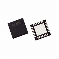
C8051F321R Silicon Laboratories Inc, C8051F321R Datasheet - Page 14

C8051F321R
Manufacturer Part Number
C8051F321R
Description
IC 8051 MCU 16K FLASH 28MLP
Manufacturer
Silicon Laboratories Inc
Series
C8051F32xr
Datasheet
1.C8051F320R.pdf
(256 pages)
Specifications of C8051F321R
Core Processor
8051
Core Size
8-Bit
Speed
25MHz
Connectivity
SMBus (2-Wire/I²C), SPI, UART/USART, USB
Peripherals
Brown-out Detect/Reset, POR, PWM, Temp Sensor, WDT
Number Of I /o
21
Program Memory Size
16KB (16K x 8)
Program Memory Type
FLASH
Ram Size
2.25K x 8
Voltage - Supply (vcc/vdd)
2.7 V ~ 3.6 V
Data Converters
A/D 13x10b
Oscillator Type
Internal
Operating Temperature
-40°C ~ 85°C
Package / Case
28-VQFN Exposed Pad, 28-HVQFN, 28-SQFN, 28-DHVQFN
Lead Free Status / RoHS Status
Contains lead / RoHS non-compliant
Eeprom Size
-
Other names
336-1067-2
- Current page: 14 of 256
- Download datasheet (4Mb)
C8051F320/1
20. PROGRAMMABLE COUNTER ARRAY (PCA0) ........................................................235
14
Figure 19.3. T0 Mode 3 Block Diagram................................................................................220
Figure 19.4. TCON: Timer Control Register.........................................................................221
Figure 19.5. TMOD: Timer Mode Register...........................................................................222
Figure 19.6. CKCON: Clock Control Register......................................................................223
Figure 19.7. TL0: Timer 0 Low Byte ....................................................................................224
Figure 19.8. TL1: Timer 1 Low Byte ....................................................................................224
Figure 19.9. TH0: Timer 0 High Byte ...................................................................................224
Figure 19.10. TH1: Timer 1 High Byte .................................................................................224
Figure 19.11. Timer 2 16-Bit Mode Block Diagram .............................................................225
Figure 19.12. Timer 2 8-Bit Mode Block Diagram ...............................................................226
Figure 19.13. Timer 2 SOF Capture Mode (T2SPLIT = ‘0’) ................................................227
Figure 19.14. Timer 2 SOF Capture Mode (T2SPLIT = ‘1’) ................................................227
Figure 19.15. TMR2CN: Timer 2 Control Register ..............................................................228
Figure 19.16. TMR2RLL: Timer 2 Reload Register Low Byte ............................................229
Figure 19.17. TMR2RLH: Timer 2 Reload Register High Byte ...........................................229
Figure 19.18. TMR2L: Timer 2 Low Byte ............................................................................229
Figure 19.19. TMR2H Timer 2 High Byte ............................................................................229
Figure 19.20. Timer 3 16-Bit Mode Block Diagram .............................................................230
Figure 19.21. Timer 3 8-Bit Mode Block Diagram ...............................................................231
Figure 19.22. Timer 3 SOF Capture Mode (T3SPLIT = ‘0’) ................................................232
Figure 19.23. Timer 3 SOF Capture Mode (T3SPLIT = ‘1’) ................................................232
Figure 19.24. TMR3CN: Timer 3 Control Register ..............................................................233
Figure 19.25. TMR3RLL: Timer 3 Reload Register Low Byte ............................................234
Figure 19.26. TMR3RLH: Timer 3 Reload Register High Byte ...........................................234
Figure 19.27. TMR3L: Timer 3 Low Byte ............................................................................234
Figure 19.28. TMR3H Timer 3 High Byte ............................................................................234
Figure 20.1. PCA Block Diagram..........................................................................................235
Figure 20.2. PCA Counter/Timer Block Diagram .................................................................236
Table 20.1. PCA Timebase Input Options............................................................................236
Figure 20.3. PCA Interrupt Block Diagram...........................................................................237
Table 20.2. PCA0CPM Register Settings for PCA Capture/Compare Modules..................237
Figure 20.4. PCA Capture Mode Diagram ............................................................................238
Figure 20.5. PCA Software Timer Mode Diagram................................................................239
Figure 20.6. PCA High Speed Output Mode Diagram ..........................................................240
Figure 20.7. PCA Frequency Output Mode ...........................................................................241
Figure 20.8. PCA 8-Bit PWM Mode Diagram ......................................................................243
Figure 20.9. PCA 16-Bit PWM Mode ...................................................................................244
Figure 20.10. PCA Module 4 with Watchdog Timer Enabled ..............................................246
Table 20.3. Watchdog Timer Timeout Intervals† ................................................................247
Figure 20.11. PCA0CN: PCA Control Register ....................................................................248
Figure 20.12. PCA0MD: PCA Mode Register ......................................................................249
Figure 20.13. PCA0CPMn: PCA Capture/Compare Mode Registers ...................................250
Figure 20.14. PCA0L: PCA Counter/Timer Low Byte .........................................................251
Figure 20.15. PCA0H: PCA Counter/Timer High Byte ........................................................251
Rev. 1.1
Related parts for C8051F321R
Image
Part Number
Description
Manufacturer
Datasheet
Request
R
Part Number:
Description:
SMD/C°/SINGLE-ENDED OUTPUT SILICON OSCILLATOR
Manufacturer:
Silicon Laboratories Inc
Part Number:
Description:
Manufacturer:
Silicon Laboratories Inc
Datasheet:
Part Number:
Description:
N/A N/A/SI4010 AES KEYFOB DEMO WITH LCD RX
Manufacturer:
Silicon Laboratories Inc
Datasheet:
Part Number:
Description:
N/A N/A/SI4010 SIMPLIFIED KEY FOB DEMO WITH LED RX
Manufacturer:
Silicon Laboratories Inc
Datasheet:
Part Number:
Description:
N/A/-40 TO 85 OC/EZLINK MODULE; F930/4432 HIGH BAND (REV E/B1)
Manufacturer:
Silicon Laboratories Inc
Part Number:
Description:
EZLink Module; F930/4432 Low Band (rev e/B1)
Manufacturer:
Silicon Laboratories Inc
Part Number:
Description:
I°/4460 10 DBM RADIO TEST CARD 434 MHZ
Manufacturer:
Silicon Laboratories Inc
Part Number:
Description:
I°/4461 14 DBM RADIO TEST CARD 868 MHZ
Manufacturer:
Silicon Laboratories Inc
Part Number:
Description:
I°/4463 20 DBM RFSWITCH RADIO TEST CARD 460 MHZ
Manufacturer:
Silicon Laboratories Inc
Part Number:
Description:
I°/4463 20 DBM RADIO TEST CARD 868 MHZ
Manufacturer:
Silicon Laboratories Inc
Part Number:
Description:
I°/4463 27 DBM RADIO TEST CARD 868 MHZ
Manufacturer:
Silicon Laboratories Inc
Part Number:
Description:
I°/4463 SKYWORKS 30 DBM RADIO TEST CARD 915 MHZ
Manufacturer:
Silicon Laboratories Inc
Part Number:
Description:
N/A N/A/-40 TO 85 OC/4463 RFMD 30 DBM RADIO TEST CARD 915 MHZ
Manufacturer:
Silicon Laboratories Inc
Part Number:
Description:
I°/4463 20 DBM RADIO TEST CARD 169 MHZ
Manufacturer:
Silicon Laboratories Inc


