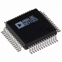
ADUC836BS Analog Devices Inc, ADUC836BS Datasheet - Page 59

ADUC836BS
Manufacturer Part Number
ADUC836BS
Description
IC ADC DUAL 16BIT W/MCU 52-MQFP
Manufacturer
Analog Devices Inc
Series
MicroConverter® ADuC8xxr
Datasheet
1.ADUC836BSZ.pdf
(80 pages)
Specifications of ADUC836BS
Rohs Status
RoHS non-compliant
Core Processor
8052
Core Size
8-Bit
Speed
12.58MHz
Connectivity
EBI/EMI, I²C, SPI, UART/USART
Peripherals
POR, PSM, PWM, Temp Sensor, WDT
Number Of I /o
34
Program Memory Size
62KB (62K x 8)
Program Memory Type
FLASH
Eeprom Size
4K x 8
Ram Size
2.25K x 8
Voltage - Supply (vcc/vdd)
2.7 V ~ 5.25 V
Data Converters
A/D 7x16b; D/A 1x12b
Oscillator Type
Internal
Operating Temperature
-40°C ~ 125°C
Package / Case
52-MQFP, 52-PQFP
Available stocks
Company
Part Number
Manufacturer
Quantity
Price
Company:
Part Number:
ADUC836BS
Manufacturer:
ADI
Quantity:
250
Part Number:
ADUC836BS
Manufacturer:
ADI/亚德诺
Quantity:
20 000
Company:
Part Number:
ADUC836BSZ
Manufacturer:
ADI
Quantity:
150
Company:
Part Number:
ADUC836BSZ
Manufacturer:
Analog Devices Inc
Quantity:
10 000
Part Number:
ADUC836BSZ
Manufacturer:
ADI/亚德诺
Quantity:
20 000
BAUD RATE GENERATION USING TIMER 1 AND TIMER 2
Timer 1 Generated Baud Rates
When Timer 1 is used as the baud rate generator, the baud rates
in Modes 1 and 3 are determined by the Timer 1 overflow rate
and the value of SMOD as follows:
The Timer 1 interrupt should be disabled in this application.
The timer itself can be configured for either timer or counter
operation, and in any of its three running modes. In the most
typical application, it is configured for timer operation, in the
Autoreload mode (high nibble of TMOD = 0100 binary). In this
case, the baud rate is given by the formula:
A very low baud rate can also be achieved with Timer 1 by leaving
the Timer 1 interrupt enabled, configuring the timer to run as a
16-bit timer (high nibble of TMOD = 0100 binary), and using
the Timer 1 interrupt to do a 16-bit software reload. Table XXXI
shows some commonly used baud rates and how they might
be calculated from a core clock frequency of 1.5728 MHz and
12.58 MHz using Timer 1. Generally speaking, a 5% error is
tolerable using asynchronous (start/stop) communications.
Ideal
Baud
9600
1600
1200
1200
REV. A
Modes 1
Mode 1
Table XXXI. Commonly Used Baud Rates, Timer 1
and Baud Rate
Core
CLK
12.58
12.58
12.58
1.57
and Mode Baud Rate
3
OSC. FREQ. IS DIVIDED BY 2, NOT 12.
NOTE AVAILABILITY OF ADDITIONAL
EXTERNAL INTERRUPT
*THE CORE CLOCK IS THE OUTPUT OF THE PLL (SEE THE ON-CHIP PLL SECTION)
TRANSITION
T2EX
SMOD
Value
1
1
1
1
DETECTOR
PIN
PIN
CORE
CLK*
T2
3
=
(
2
SMOD
TH1-Reload
Value
–7 (F9H)
–27 (E5H)
–55 (C9H)
–7 (F9H)
2
⁄
32
=
C/ T2 = 0
C/ T2 = 1
)
32 12 256
×
EXEN2
2
(
×
Timer Overflow Rate
SMOD
CONTROL
CONTROL
Figure 56.Timer 2, UART Baud Rates
Actual
9362
1627
1192
1170
(
Baud
TR2
1
×
f
CORE
−
EXF 2
TH
1
%
Error
2.5
1.1
0.7
2.5
)
RCAP2L
(8 BITS)
TL2
TIMER 2
INTERRUPT
)
–59–
RCAP2H
(8 BITS)
Timer 2 Generated Baud Rates
Baud rates can also be generated using Timer 2. Using Timer 2 is
similar to using Timer 1 in that the timer must overflow 16 times
before a bit is transmitted/received. Because Timer 2 has a 16-bit
Autoreload mode, a wider range of baud rates is possible.
Therefore when Timer 2 is used to generate baud rates, the timer
increments every two clock cycles and not every core machine
cycle as before.Thus, it increments six times faster than Timer 1,
and therefore baud rates six times faster are possible. Because
Timer 2 has a 16-bit autoreload capability, very low baud rates
are still possible.
Timer 2 is selected as the baud rate generator by setting the TCLK
and/or RCLK in T2CON.The baud rates for transmit and receive
can be simultaneously different. Setting RCLK and/or TCLK puts
Timer 2 into its baud rate generator mode, as shown in Figure 56.
In this case, the baud rate is given by the formula:
Table XXXII shows some commonly used baud rates and
how they might be calculated from a core clock frequency of
1.5728 MHz and 12.5829 MHz using Timer 2.
Ideal
Baud
19200
9600
1600
1200
9600
1600
1200
TH2
Mode 1
Mode 1
Table XXXII. Commonly Used Baud Rates, Timer 2
RELOAD
OVERFLOW
and Mode Baud Rate
TIMER 2
and Mode Baud Rate
Core
CLK
12.58
12.58
12.58
12.58
1.57
1.57
1.57
3
3
RCAP2H
Value
–1 (FFH)
–1 (FFH)
–1 (FFH)
–2 (FEH)
–1 (FFH)
–1 (FFH)
–1 (FFH)
1
1
OVERFLOW
2
TIMER 1
0
0
0
1
=
RCLK
TCLK
(
RCAP2L
Value
–20 (ECH)
–41 (D7H)
–164 (5CH) 2398
–72 (B8H)
–5 (FBH)
–20 (ECH)
–41 (D7H)
1 16
=
16
16
32
SMOD
)
×
×
(
(
RX
CLOCK
TX
CLOCK
Timer Overflow Rate
65536
ADuC836
Actual
Baud
19661
9591
1199
9830
1658
1199
f
CORE
2
−
RCAP H L
2
%
Error
2.4
0.1
0.1
0.1
2.4
2.4
0.1
)
)


