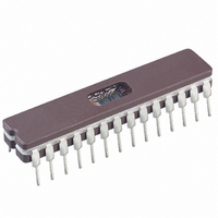
PIC16C745/JW Microchip Technology, PIC16C745/JW Datasheet - Page 67

PIC16C745/JW
Manufacturer Part Number
PIC16C745/JW
Description
IC MCU EPROM8KX14 USB A/D 28CDIP
Manufacturer
Microchip Technology
Series
PIC® 16Cr
Datasheets
1.PIC16F616T-ISL.pdf
(8 pages)
2.PIC16C745-ISP.pdf
(165 pages)
3.PIC16C745-ISP.pdf
(6 pages)
4.PIC16C745-ISP.pdf
(6 pages)
Specifications of PIC16C745/JW
Core Processor
PIC
Core Size
8-Bit
Speed
24MHz
Connectivity
SCI, UART/USART, USB
Peripherals
Brown-out Detect/Reset, POR, PWM, WDT
Number Of I /o
22
Program Memory Size
14KB (8K x 14)
Program Memory Type
EPROM, UV
Ram Size
256 x 8
Voltage - Supply (vcc/vdd)
4.35 V ~ 5.25 V
Data Converters
A/D 5x8b
Oscillator Type
External
Operating Temperature
0°C ~ 70°C
Package / Case
28-CDIP (0.300", 7.62mm) Window
Lead Free Status / RoHS Status
Contains lead / RoHS non-compliant
Eeprom Size
-
Available stocks
Company
Part Number
Manufacturer
Quantity
Price
Company:
Part Number:
PIC16C745/JW
Manufacturer:
MICROCHIP
Quantity:
51
Part Number:
PIC16C745/JW
Manufacturer:
MICROCHIP/微芯
Quantity:
20 000
10.5.1.9
Each endpoint is controlled by an Endpoint Control
Register.
Descriptors (BD) for the following endpoints:
The user will be required to disable unused Endpoints
and directions using the Endpoint Control Registers.
REGISTER 10-9: USB ENDPOINT CONTROL REGISTER (UEPn: 198H-19Ah)
2000 Microchip Technology Inc.
bit7
bit 7-4: Unimplemented: Read as ’0’
bit 3-1: EP_CTL_DIS, EP_OUT_EN, EP_IN_EN: These three bits define if an endpoint is enabled and the direc-
bit 0:
U-0
- EP0 Out
- EP0 In
- EP1 Out
- EP1 In
- EP2 Out
- EP2 In
—
Endpoint Registers
The
tion of the endpoint. The endpoint enable/direction control is defined as follows:
control bits in the Endpoint Enable register, but is only valid if EP_IN_EN=1 or EP_OUT_EN=1. Any access
to this endpoint will cause the USB to return a STALL handshake. The EP_STALL bit can be set or cleared
by the SIE. Refer to the USB 1.1 Specification, Sections 4.4.4 and 8.5.2 for more details on the STALL
protocol.
U-0
EP_STALL: When this bit is set it indicates that the endpoint is stalled. This bit has priority over all other
EP_CTL_DIS EP_OUT_EN
—
X
X
X
1
0
PIC16C745/765
U-0
—
U-0
—
0
0
1
1
1
EP_CTL_DIS EP_OUT_EN EP_IN_EN EP_STALL
supports
R/W-0
EP_IN_EN
Buffer
0
1
0
1
1
Preliminary
R/W-0
Endpoint Enable/Direction Control
Disable Endpoint
Enable Endpoint for IN tokens only
Enable Endpoint for OUT tokens only
Enable Endpoint for IN and OUT tokens
Enable Endpoint for IN, OUT, and SETUP tokens
10.5.1.10 USB Endpoint Control Register (EPCn)
The Endpoint Control Register contains the endpoint
control bits for each of the 6 endpoints available on
USB for a decoded address. These four bits define the
control necessary for any one endpoint. Endpoint 0
(ENDP0) is associated with control pipe 0 which is
required by USB for all functions (IN, OUT, and
SETUP). Therefore, after a USB_RST interrupt has
been received, the microprocessor should set UEP0 to
contain 06h.
Note:
R/W-0
These registers are initialized in response
to a RESET from the host. The user
must
USB_CH9.ASM to configure the endpoints
as needed for the application.
PIC16C745/765
R/W-0
modify
bit0
function
R = Readable bit
W = Writable bit
U = Unimplemented bit,
-n = Value at POR reset
read as ‘0’
DS41124C-page 67
USBReset
in


