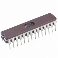
PIC16C745/JW Microchip Technology, PIC16C745/JW Datasheet - Page 66

PIC16C745/JW
Manufacturer Part Number
PIC16C745/JW
Description
IC MCU EPROM8KX14 USB A/D 28CDIP
Manufacturer
Microchip Technology
Series
PIC® 16Cr
Datasheets
1.PIC16F616T-ISL.pdf
(8 pages)
2.PIC16C745-ISP.pdf
(165 pages)
3.PIC16C745-ISP.pdf
(6 pages)
4.PIC16C745-ISP.pdf
(6 pages)
Specifications of PIC16C745/JW
Core Processor
PIC
Core Size
8-Bit
Speed
24MHz
Connectivity
SCI, UART/USART, USB
Peripherals
Brown-out Detect/Reset, POR, PWM, WDT
Number Of I /o
22
Program Memory Size
14KB (8K x 14)
Program Memory Type
EPROM, UV
Ram Size
256 x 8
Voltage - Supply (vcc/vdd)
4.35 V ~ 5.25 V
Data Converters
A/D 5x8b
Oscillator Type
External
Operating Temperature
0°C ~ 70°C
Package / Case
28-CDIP (0.300", 7.62mm) Window
Lead Free Status / RoHS Status
Contains lead / RoHS non-compliant
Eeprom Size
-
Available stocks
Company
Part Number
Manufacturer
Quantity
Price
Company:
Part Number:
PIC16C745/JW
Manufacturer:
MICROCHIP
Quantity:
51
Part Number:
PIC16C745/JW
Manufacturer:
MICROCHIP/微芯
Quantity:
20 000
PIC16C745/765
10.5.1.7
The Address Register (UADDR) contains the unique
USB address that the USB will decode. The register is
reset to 00h after the RESET input has gone active or
the USB has decoded a USB Reset signaling. That will
initialize the address register to decode address 00h
as required by the USB specification. The USB
address must be written by the MCU during the USB
SETUP phase.
REGISTER 10-7: USB ADDRESS REGISTER (UADDR: 196h)
10.5.1.8
This register is used by the USB firmware libraries for
USB status.
REGISTER 10-8: RESERVED SOFTWARE LIBRARY REGISTER (USWSTAT: 197H):.
DS41124C-page 66
Warning: Writing to this register may cause the
bit7
bit 7:
bit 6-0: ADDR<6:0>: This 7-bit value defines the USB address that the USB will decode
bit 7-2
bit 1-0: W Enumeration Status <1:0>: Status of USB peripheral during enumeration
R/W-0
Note 1: Application should not modify these bits.
U-0
—
7
(1)
:Reserved: Read as “X’
USB Address Register (UADDR)
USB Software Status Register (USWSTAT)
Unimplemented: Read as ’0’
00 = Powered
01 = Default
10 = Addressed
11 = Configured
R/W-0
ADDR6
SIE to drop off the Bus.
R/W-0
6
Reserved for CH9 Firmware
R/W-0
ADDR5
R/W-0
5
R/W-0
ADDR4
R/W-0
4
R/W-0
ADDR3
R/W-0
3
Preliminary
R/W-0
ADDR2
R/W-0
2
Enumeration Status
R/W-0
ADDR1
R/W-0
1
ADDR0
R/W-0
R/W-0
0
bit0
2000 Microchip Technology Inc.
R = Readable bit
W = Writable bit
U = Unimplemented bit,
-n = Value at POR reset
R = Readable bit
W = Writable bit
U = Unimplemented bit,
-n = Value at POR reset
read as ‘0’
read as ‘0’


