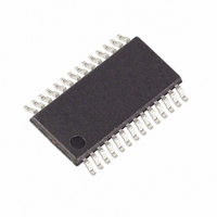
MAXQ3108-FFN+ Maxim Integrated Products, MAXQ3108-FFN+ Datasheet - Page 38

MAXQ3108-FFN+
Manufacturer Part Number
MAXQ3108-FFN+
Description
IC MCU DUAL-CORE 16BIT 28-TSSOP
Manufacturer
Maxim Integrated Products
Series
MAXQ™r
Datasheet
1.MAXQ3108-FFN.pdf
(64 pages)
Specifications of MAXQ3108-FFN+
Core Processor
RISC
Core Size
16-Bit
Speed
10MHz
Connectivity
I²C, SPI, UART/USART
Peripherals
POR, PWM, WDT
Number Of I /o
21
Program Memory Size
64KB (32K x 16)
Program Memory Type
FLASH
Ram Size
11K x 8
Voltage - Supply (vcc/vdd)
1.8 V ~ 3.6 V
Oscillator Type
External
Operating Temperature
-40°C ~ 85°C
Package / Case
28-TSSOP
Processor Series
MAXQ
Core
RISC
Data Bus Width
16 bit
Data Ram Size
2 KB
Interface Type
I2C, JTAG, SPI
Maximum Clock Frequency
10 MHz
Number Of Programmable I/os
22
Number Of Timers
2
Operating Supply Voltage
3.6 V
Maximum Operating Temperature
+ 85 C
Mounting Style
SMD/SMT
Minimum Operating Temperature
- 40 C
Lead Free Status / RoHS Status
Lead free / RoHS Compliant
Eeprom Size
-
Data Converters
-
Lead Free Status / Rohs Status
Lead free / RoHS Compliant
Low-Power, Dual-Core Microcontroller
38
T2CFG.[2:1]: CCF[1:0]
T2CFG.3: T2MD
T2CFG.[6:4]: T2DIV[2:0]
T2CFG.7: T2CI
MCNT (00h, 03h)
Initialization:
Read/Write Access:
MCNT.0: SUS
MCNT.1: MMAC
______________________________________________________________________________________
Timer 2 Capture/Compare Function Select. These bits, in conjunction with the C/T2 bit, select the
basic operating mode of timer 2. In the dual 8-bit mode of operation (T2MD = 1), the secondary
timer (T2L) always operates in compare mode.
Timer 2 Mode Select. This bit enables the dual 8-bit mode of operation. The default reset state is
0, which selects the 16-bit mode of operation. When the dual 8-bit mode is established, the primary
timer/counter (T2H) carries all the counter/capture functionality with it while the secondary 8- bit
timer (T2L) must operate in timer compare mode, sourcing the defined internal clock.
Timer 2 Clock Divide 2:0 Bits. These three bits select the divide ratio for the timer clock when
operating in timer mode.
Timer 2 Clock Input Select Bit. Setting this bit enables an alternate input clock source to the timer
2 block. The alternate input clock selection is the 32kHz clock. The alternate input clock must be
sampled by the system clock, which requires that the system clock be at least 4 x 32kHz for
proper operation.
Multiplier Control Register
This register is cleared to 0000h on all forms of reset.
Unrestricted read, write is allowed for all bits except bit 7 and 15. Bit 7 and 15 are read-only.
Signed-Unsigned. This bit determines the data type of the operands. When this bit is cleared to 0,
the multiplier performs a signed operation; the operands are two’s complement values. When this
bit is set to logic 1, the multiplier performs an unsigned operation with the operands as absolute
magnitudes.
Multiply-Accumulate Enable
0: 16-bit mode (default)
1: dual 8-bit mode
Special Function Register Bit Descriptions (continued)
CCF[1:0]
00
01
10
11
T2DIV[2:0]
000
001
010
011
100
101
110
111
Rising and Falling
EDGE(S)
Falling
Rising
None
C/T2 = 0 (TIMER
Capture/Reload
Capture/Reload
Capture/Reload
Compare Mode
MODE)
DIVIDE RATIO
128
16
32
64
1
2
4
8
C/T2 = 1 (COUNTER
Disabled
Counter
Counter
Counter
MODE)


