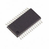
MAXQ3108-FFN+ Maxim Integrated Products, MAXQ3108-FFN+ Datasheet - Page 32

MAXQ3108-FFN+
Manufacturer Part Number
MAXQ3108-FFN+
Description
IC MCU DUAL-CORE 16BIT 28-TSSOP
Manufacturer
Maxim Integrated Products
Series
MAXQ™r
Datasheet
1.MAXQ3108-FFN.pdf
(64 pages)
Specifications of MAXQ3108-FFN+
Core Processor
RISC
Core Size
16-Bit
Speed
10MHz
Connectivity
I²C, SPI, UART/USART
Peripherals
POR, PWM, WDT
Number Of I /o
21
Program Memory Size
64KB (32K x 16)
Program Memory Type
FLASH
Ram Size
11K x 8
Voltage - Supply (vcc/vdd)
1.8 V ~ 3.6 V
Oscillator Type
External
Operating Temperature
-40°C ~ 85°C
Package / Case
28-TSSOP
Processor Series
MAXQ
Core
RISC
Data Bus Width
16 bit
Data Ram Size
2 KB
Interface Type
I2C, JTAG, SPI
Maximum Clock Frequency
10 MHz
Number Of Programmable I/os
22
Number Of Timers
2
Operating Supply Voltage
3.6 V
Maximum Operating Temperature
+ 85 C
Mounting Style
SMD/SMT
Minimum Operating Temperature
- 40 C
Lead Free Status / RoHS Status
Lead free / RoHS Compliant
Eeprom Size
-
Data Converters
-
Lead Free Status / Rohs Status
Lead free / RoHS Compliant
Low-Power, Dual-Core Microcontroller
32
T2CNA.1: SS2
T2CNA.2: CPRL2
T2CNA.3: TR2
T2CNA.4: TR2L
T2CNA.5: T2POL0
______________________________________________________________________________________
Single Shot. This bit is used to automatically override or delay the effect of the TR2 bit setting. The
single-shot bit is only useful in the timer mode of operation (C/T2 = 0) and should not be set to 1
when the counter mode of operation is enabled (C/T2 = 1).
Compare Mode: If SS2 is written to a 1 while in compare mode, one cycle of the defined waveform
(reload to overflow) is output to the T2P, T2PB pins as prescribed by T2POL[1:0] and T2OE[1:0]
controls. The only time that this does not immediately occur is when a gating condition is also
defined. If a gating condition is defined, the single-shot cycle cannot occur until the gating
condition is removed. If the specified nongated level is already in effect, the single-shot period
starts. The gated single-shot output is not supported in dual 8-bit mode.
Capture Mode: If SS2 is written to a 1 while in capture mode, the timer is halted and the single-shot
capture cycle does not begin until 1) the edge specified by CCF[1:0] is detected or 2) the defined
gating condition is removed. Once running, the timer continues running (as allowed by the gate
condition) until the defined capture single-shot edge is detected. In this way, the SS2 bit can be
used to delay the running of a timer until an edge is detected (setting both SS2 and TR2 = 1) or
override the TR2 = 0 bit setting for one capture cycle (setting only SS2 = 1). When both edges are
defined for capture CCF[1:0] = 11b, the T2POL0 bit serves to define the single-shot start/end edge:
falling edge if T2POL0 = 1; rising edge if T2POL0 = 0. No interrupt flag is set when the starting
edge for the single-shot capture cycle is detected. The single-shot capture cycle always ends
when the next single-shot edge is detected. The start/end edge is defined by T2POL0. This bit is
intended to automate pulse-width measurement (low or high) and duty cycle/period measurement.
Capture and Reload Enable. This bit enables a reload (in addition to a capture) on the edge
specified by CCF[1:0] when operating in capture/reload mode (C/T2 = 0). If both edges are defined
for capture/reload (CCF[1:0] = 11b), enabling the gating control (G2EN = 1) allows the T2POL0 bit to
be used to prevent a reload on one of the edges. If T2POL0 is 0, no reload on the falling edge; if
T2POL0 is 1, no reload on the rising edge.
Timer 2 Run Enable. This bit starts/stop timer 2. In the dual 8-bit mode of operation, this bit applies
only to the T2H timer/counter. Otherwise, the bit applies to the full 16-bit T2H:T2L timer/counter.
When the timer is stopped (TR2 = 0), the timer registers hold their count. The single-shot bit (SS2)
can override and/or delay the effect of the TR2 bit.
Timer 2 Low Run Enable. This bit starts/stops the low 8-bit timer (T2L) when dual 8-bit mode (T2MD
= 1) is in effect. This bit has no effect when T2MD = 0.
Timer 2 Polarity Select 0. When the timer 2 output function has been enabled (T2OE0 = 1), the
polarity select bit defines the starting logic level for the T2P output waveform. When T2POL0 = 0,
the starting state for the T2P output is logic-low. When T2POL0 = 1, the starting state for the T2P
output is logic-high. The T2POL0 bit can be modified any time, but takes effect on the external pin
when T2OE0 is changed from 0 to 1. When the timer 2 pin is being used as an input (T2OE0 = 0),
the polarity select bit defines which logic level can be used to gate the timer input clock (when
CCF[1:0] <> 11b). When CCF[1:0] = 11b, T2POL0 defines which edge can start/stop a single-shot
capture and which edge reload can be skipped (if CPRL2 = 1 and G2EN = 1).
0: capture on edge(s) specified by CCF[1:0] bits
1: capture and reload on edge(s) specified by CCF[1:0] bits
0: timer 2 stopped
1: timer 2 run
0: timer 2 low stopped
1: timer 2 low run
Special Function Register Bit Descriptions (continued)


