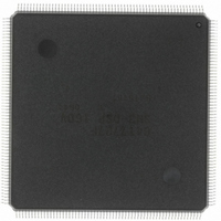
HD6417727F160CV Renesas Electronics America, HD6417727F160CV Datasheet - Page 231

HD6417727F160CV
Manufacturer Part Number
HD6417727F160CV
Description
IC SH MPU ROMLESS 240QFN
Manufacturer
Renesas Electronics America
Series
SuperH® SH7700r
Datasheet
1.HD6417727BP100CV.pdf
(1098 pages)
Specifications of HD6417727F160CV
Core Processor
SH-3 DSP
Core Size
32-Bit
Speed
160MHz
Connectivity
FIFO, SCI, SIO, SmartCard, USB
Peripherals
DMA, LCD, POR, WDT
Number Of I /o
104
Program Memory Type
ROMless
Ram Size
32K x 8
Voltage - Supply (vcc/vdd)
1.7 V ~ 2.05 V
Data Converters
A/D 6x10b; D/A 2x8b
Oscillator Type
Internal
Operating Temperature
-20°C ~ 75°C
Package / Case
240-QFP
Lead Free Status / RoHS Status
Lead free / RoHS Compliant
Eeprom Size
-
Program Memory Size
-
Available stocks
Company
Part Number
Manufacturer
Quantity
Price
Company:
Part Number:
HD6417727F160CV
Manufacturer:
RENESAS
Quantity:
37
Company:
Part Number:
HD6417727F160CV
Manufacturer:
RENESAS
Quantity:
753
- Current page: 231 of 1098
- Download datasheet (7Mb)
Section 7 Interrupt Controller (INTC)
• User-debugging interface (H-UDI)
• Serial IO (SIOF)
Not every interrupt source is assigned a different interrupt vector. Sources are reflected on the
interrupt event register (INTEVT and INTEVT2). It is easy to identify sources by using the values
of the INTEVT or INTEVT2 register as branch offsets.
The priority level (from 0 to 15) can be set for each module except for H-UDI by writing to the
interrupt priority setting registers A to G (IPRA to IPRG). The priority level of H-UDI interrupt is
15 (fixed).
The interrupt mask bits (I3 to I0) of the status register are not affected by the on-chip supporting
module interrupt processing.
TMU and RTC interrupts can wake the chip up from the standby state when the relevant interrupt
level is higher than I3 to I0 in the SR register (but only when the RTC 32-kHz oscillator is used).
7.2.6
Interrupt Exception Handling and Priority
Tables 7.4 and 7.5 list the codes for the interrupt event register (INTEVT and INTEVT2), and the
order of interrupt priority. Each interrupt source is assigned unique code. The start address of the
interrupt service routine is common to each interrupt source. This is why, for instance, the value of
INTEVT or INTEVT2 is used as offset at the start of the interrupt service routine and branched to
identify the interrupt source.
The order of priority of the on-chip supporting module, IRQ, and PINT interrupts is set within the
priority levels 0 to 15 at will by using the interrupt priority level set to registers A to G (IPRA to
IPRG). The order of priority of the on-chip supporting module, IRQ, and PINT interrupts is set to
zero by RESET.
When the order of priorities for multiple interrupt sources are set to the same level and such
interrupts are generated at the same time, they are processed according to the default order listed
in tables 7.4 and 7.5.
Rev.6.00 Mar. 27, 2009 Page 173 of 1036
REJ09B0254-0600
Related parts for HD6417727F160CV
Image
Part Number
Description
Manufacturer
Datasheet
Request
R

Part Number:
Description:
KIT STARTER FOR M16C/29
Manufacturer:
Renesas Electronics America
Datasheet:

Part Number:
Description:
KIT STARTER FOR R8C/2D
Manufacturer:
Renesas Electronics America
Datasheet:

Part Number:
Description:
R0K33062P STARTER KIT
Manufacturer:
Renesas Electronics America
Datasheet:

Part Number:
Description:
KIT STARTER FOR R8C/23 E8A
Manufacturer:
Renesas Electronics America
Datasheet:

Part Number:
Description:
KIT STARTER FOR R8C/25
Manufacturer:
Renesas Electronics America
Datasheet:

Part Number:
Description:
KIT STARTER H8S2456 SHARPE DSPLY
Manufacturer:
Renesas Electronics America
Datasheet:

Part Number:
Description:
KIT STARTER FOR R8C38C
Manufacturer:
Renesas Electronics America
Datasheet:

Part Number:
Description:
KIT STARTER FOR R8C35C
Manufacturer:
Renesas Electronics America
Datasheet:

Part Number:
Description:
KIT STARTER FOR R8CL3AC+LCD APPS
Manufacturer:
Renesas Electronics America
Datasheet:

Part Number:
Description:
KIT STARTER FOR RX610
Manufacturer:
Renesas Electronics America
Datasheet:

Part Number:
Description:
KIT STARTER FOR R32C/118
Manufacturer:
Renesas Electronics America
Datasheet:

Part Number:
Description:
KIT DEV RSK-R8C/26-29
Manufacturer:
Renesas Electronics America
Datasheet:

Part Number:
Description:
KIT STARTER FOR SH7124
Manufacturer:
Renesas Electronics America
Datasheet:

Part Number:
Description:
KIT STARTER FOR H8SX/1622
Manufacturer:
Renesas Electronics America
Datasheet:

Part Number:
Description:
KIT DEV FOR SH7203
Manufacturer:
Renesas Electronics America
Datasheet:


