DF36054GFPJ Renesas Electronics America, DF36054GFPJ Datasheet - Page 119
DF36054GFPJ
Manufacturer Part Number
DF36054GFPJ
Description
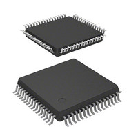
MCU 3/5V 32K J-TEMP POR&LVD 64-Q
Manufacturer
Renesas Electronics America
Series
H8® H8/300H Tinyr
Datasheet
1.DF36057GFZV.pdf
(594 pages)
Specifications of DF36054GFPJ
Core Processor
H8/300H
Core Size
16-Bit
Speed
20MHz
Connectivity
CAN, SCI, SSU
Peripherals
LVD, POR, PWM, WDT
Number Of I /o
45
Program Memory Size
32KB (32K x 8)
Program Memory Type
FLASH
Ram Size
2K x 8
Voltage - Supply (vcc/vdd)
3 V ~ 5.5 V
Data Converters
A/D 8x10b
Oscillator Type
Internal
Operating Temperature
-40°C ~ 85°C
Package / Case
64-LQFP
Lead Free Status / RoHS Status
Contains lead / RoHS non-compliant
Eeprom Size
-
Other names
HD64F36054GFPJ
HD64F36054GFPJ
HD64F36054GFPJ


Standby mode is cleared by an interrupt. When an interrupt is requested, the system clock pulse
generator starts. After the time set in bits STS2 to STS0 in SYSCR1 has elapsed, and interrupt
exception handling starts. Standby mode is not cleared if the I bit of CCR is set to 1 or the
requested interrupt is disabled in the interrupt enable register.
When the RES pin goes low, the system clock pulse generator starts. Since system clock signals
are supplied to the entire chip as soon as the system clock pulse generator starts functioning, the
RES pin must be kept low until the pulse generator output stabilizes. After the pulse generator
output has stabilized, the CPU starts reset exception handling if the RES pin is driven high.
6.2.3
In subsleep mode, operation of the CPU and on-chip peripheral modules is halted. As long as a
required voltage is applied, the contents of CPU registers, the on-chip RAM, and some registers of
the on-chip peripheral modules are retained. I/O ports keep the same states as before the transition.
Subsleep mode is cleared by an interrupt. When an interrupt is requested, subsleep mode is cleared
and interrupt exception handling starts. Subsleep mode is not cleared if the I bit of CCR is set to 1
or the requested interrupt is disabled in the interrupt enable register. After subsleep mode is
cleared, a transition is made to active mode when the LSON bit in SYSCR2 is 0, and a transition is
made to subactive mode when the bit is 1. After the time set in bits STS2 to STS0 in SYSCR1 has
elapsed, a transition is made to active mode.
When the RES pin goes low, the system clock pulse generator starts. Since system clock signals
are supplied to the entire chip as soon as the system clock pulse generator starts functioning, the
RES pin must be kept low until the pulse generator output stabilizes. After the pulse generator
output has stabilized, the CPU starts reset exception handling if the RES pin is driven high.
6.2.4
The operating frequency of subactive mode is selected from
SA0 bits in SYSCR2. After the SLEEP instruction is executed, the operating frequency changes to
the frequency which is set before the execution. When the SLEEP instruction is executed in
subactive mode, a transition to sleep mode, subsleep mode, standby mode, active mode, or
subactive mode is made, depending on the combination of SYSCR1 and SYSCR2. When the RES
pin goes low, the system clock pulse generator starts. Since system clock signals are supplied to
the entire chip as soon as the system clock pulse generator starts functioning, the RES pin must be
kept low until the pulse generator output stabilizes. After the pulse generator output has stabilized,
the CPU starts reset exception handling if the RES pin is driven high.
Subsleep Mode
Subactive Mode
W
Rev. 4.00 Mar. 15, 2006 Page 85 of 556
/2,
W
/4, and
Section 6 Power-Down Modes
W
/8 by the SA1 and
REJ09B0026-0400
Related parts for DF36054GFPJ
Image
Part Number
Description
Manufacturer
Datasheet
Request
R

Part Number:
Description:
Headers & Wire Housings 20P PLUG METAL COVER
Manufacturer:
Hirose Electric Co Ltd
Part Number:
Description:
Headers & Wire Housings 25P PLUG METAL COVER
Manufacturer:
Hirose Electric Co Ltd
Part Number:
Description:
Headers & Wire Housings 15P PLUG METAL COVER
Manufacturer:
Hirose Electric Co Ltd

Part Number:
Description:
0.4 Mm Pitch, 1.5 Mm Mated Height, Board-to-fine Coaxial Cable Connectors
Manufacturer:
Hirose Electric
Datasheet:
Part Number:
Description:
CONN RECEPT 40POS 0.4MM SMD GOLD
Manufacturer:
Hirose Electric Co Ltd
Datasheet:

Part Number:
Description:
KIT STARTER FOR M16C/29
Manufacturer:
Renesas Electronics America
Datasheet:

Part Number:
Description:
KIT STARTER FOR R8C/2D
Manufacturer:
Renesas Electronics America
Datasheet:

Part Number:
Description:
R0K33062P STARTER KIT
Manufacturer:
Renesas Electronics America
Datasheet:

Part Number:
Description:
KIT STARTER FOR R8C/23 E8A
Manufacturer:
Renesas Electronics America
Datasheet:

Part Number:
Description:
KIT STARTER FOR R8C/25
Manufacturer:
Renesas Electronics America
Datasheet:

Part Number:
Description:
KIT STARTER H8S2456 SHARPE DSPLY
Manufacturer:
Renesas Electronics America
Datasheet:

Part Number:
Description:
KIT STARTER FOR R8C38C
Manufacturer:
Renesas Electronics America
Datasheet:

Part Number:
Description:
KIT STARTER FOR R8C35C
Manufacturer:
Renesas Electronics America
Datasheet:

Part Number:
Description:
KIT STARTER FOR R8CL3AC+LCD APPS
Manufacturer:
Renesas Electronics America
Datasheet:
Part Number:
Description:
KIT STARTER FOR RX610
Manufacturer:
Renesas Electronics America
Datasheet: