DF36034GFPJ Renesas Electronics America, DF36034GFPJ Datasheet - Page 18
DF36034GFPJ
Manufacturer Part Number
DF36034GFPJ
Description
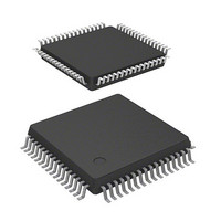
MCU 3/5V 32K J-TEMP POR&LVD 64-L
Manufacturer
Renesas Electronics America
Series
H8® H8/300H Tinyr
Datasheet
1.DF36057GFZV.pdf
(594 pages)
Specifications of DF36034GFPJ
Core Processor
H8/300H
Core Size
16-Bit
Speed
20MHz
Connectivity
CAN, SCI, SSU
Peripherals
LVD, POR, PWM, WDT
Number Of I /o
45
Program Memory Size
32KB (32K x 8)
Program Memory Type
FLASH
Ram Size
2K x 8
Voltage - Supply (vcc/vdd)
3 V ~ 5.5 V
Data Converters
A/D 8x10b
Oscillator Type
Internal
Operating Temperature
-40°C ~ 85°C
Package / Case
64-LQFP
Lead Free Status / RoHS Status
Contains lead / RoHS non-compliant
Eeprom Size
-
Other names
HD64F36034GFPJ
HD64F36034GFPJ
HD64F36034GFPJ


15.5
15.6
15.7
15.8
15.9
Section 16 Synchronous Serial Communication Unit (SSU) ............................ 349
16.1
16.2
16.3
16.4
Rev. 4.00 Mar. 15, 2006 Page xvi of xxxii
15.4.1
15.4.2
15.4.3
Operation .......................................................................................................................... 324
15.5.1
15.5.2
15.5.3
15.5.4
15.5.5
15.5.6
Interrupt Requests............................................................................................................. 344
Test Mode Settings ........................................................................................................... 345
CAN Bus Interface ........................................................................................................... 346
Usage Notes ...................................................................................................................... 347
Features............................................................................................................................. 349
Continuous transmission and reception of serial data are enabled since both transmitter
and Input/Output Pins ....................................................................................................... 349
Register Descriptions........................................................................................................ 350
16.3.1
16.3.2
16.3.3
16.3.4
16.3.5
16.3.6
16.3.7
16.3.8
Operation .......................................................................................................................... 359
16.4.1
16.4.2
16.4.3
16.4.4
16.4.5
16.4.6
16.4.7
16.4.8
16.4.9
16.4.10 SCS Pin Control and Arbitration ...................................................................... 376
Local Acceptance Filter Mask
(LAFMHn1, LAFMHn0, LAFMLn1, LAFMLn0 [n = 0 to 3]) ........................ 322
Message Control (MCn0, MCn4 to MCn7 [n = 0 to 3]) ................................... 319
Message Data (MDn0 to MDn7 [n = 0 to 3]) ................................................... 323
TinyCAN Initial Settings .................................................................................. 324
Bit Timing......................................................................................................... 325
Message Transmission...................................................................................... 327
Message Reception ........................................................................................... 336
Reconfiguring Mailbox..................................................................................... 340
TinyCAN Standby Transition ........................................................................... 342
SS Control Register H (SSCRH) ...................................................................... 351
SS Control Register L (SSCRL) ....................................................................... 353
SS Mode Register (SSMR) ............................................................................... 354
SS Enable Register (SSER) .............................................................................. 355
SS Status Register (SSSR)................................................................................ 356
SS Receive Data Register (SSRDR) ................................................................. 358
SS Transmit Data Register (SSTDR)................................................................ 358
SS Shift Register (SSTRSR)............................................................................. 358
Transfer Clock .................................................................................................. 359
Relationship between Clock Polarity and Phase, and Data............................... 359
Relationship between Data Input/Output Pin and Shift Register ...................... 361
Communication Modes and Pin Functions ....................................................... 362
Operation in Clocked Synchronous Communication Mode ............................. 363
Operation in Four-Line Bus Communication Mode ......................................... 370
Initialization in Four-Line Bus Communication Mode..................................... 371
Serial Data Transmission .................................................................................. 372
Serial Data Reception ....................................................................................... 374
Related parts for DF36034GFPJ
Image
Part Number
Description
Manufacturer
Datasheet
Request
R

Part Number:
Description:
Headers & Wire Housings 20P PLUG METAL COVER
Manufacturer:
Hirose Electric Co Ltd
Part Number:
Description:
Headers & Wire Housings 25P PLUG METAL COVER
Manufacturer:
Hirose Electric Co Ltd
Part Number:
Description:
Headers & Wire Housings 15P PLUG METAL COVER
Manufacturer:
Hirose Electric Co Ltd

Part Number:
Description:
0.4 Mm Pitch, 1.5 Mm Mated Height, Board-to-fine Coaxial Cable Connectors
Manufacturer:
Hirose Electric
Datasheet:
Part Number:
Description:
CONN RECEPT 40POS 0.4MM SMD GOLD
Manufacturer:
Hirose Electric Co Ltd
Datasheet:

Part Number:
Description:
KIT STARTER FOR M16C/29
Manufacturer:
Renesas Electronics America
Datasheet:

Part Number:
Description:
KIT STARTER FOR R8C/2D
Manufacturer:
Renesas Electronics America
Datasheet:

Part Number:
Description:
R0K33062P STARTER KIT
Manufacturer:
Renesas Electronics America
Datasheet:

Part Number:
Description:
KIT STARTER FOR R8C/23 E8A
Manufacturer:
Renesas Electronics America
Datasheet:

Part Number:
Description:
KIT STARTER FOR R8C/25
Manufacturer:
Renesas Electronics America
Datasheet:

Part Number:
Description:
KIT STARTER H8S2456 SHARPE DSPLY
Manufacturer:
Renesas Electronics America
Datasheet:

Part Number:
Description:
KIT STARTER FOR R8C38C
Manufacturer:
Renesas Electronics America
Datasheet:

Part Number:
Description:
KIT STARTER FOR R8C35C
Manufacturer:
Renesas Electronics America
Datasheet:

Part Number:
Description:
KIT STARTER FOR R8CL3AC+LCD APPS
Manufacturer:
Renesas Electronics America
Datasheet:
Part Number:
Description:
KIT STARTER FOR RX610
Manufacturer:
Renesas Electronics America
Datasheet: