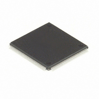
MC68HC16Z1CAG25 Freescale Semiconductor, MC68HC16Z1CAG25 Datasheet - Page 96

MC68HC16Z1CAG25
Manufacturer Part Number
MC68HC16Z1CAG25
Description
IC MCU 16BIT 25MHZ 144-LQFP
Manufacturer
Freescale Semiconductor
Series
HC16r
Datasheet
1.MC68HC16Z1VEH16.pdf
(500 pages)
Specifications of MC68HC16Z1CAG25
Core Processor
CPU16
Core Size
16-Bit
Speed
25MHz
Connectivity
EBI/EMI, SCI, SPI
Peripherals
POR, PWM, WDT
Number Of I /o
16
Program Memory Type
ROMless
Ram Size
1K x 8
Voltage - Supply (vcc/vdd)
2.7 V ~ 5.5 V
Data Converters
A/D 8x10b
Oscillator Type
Internal
Operating Temperature
-40°C ~ 85°C
Package / Case
144-LQFP
Cpu Family
HC16
Device Core Size
16b
Frequency (max)
25MHz
Interface Type
SCI/SPI/UART
Program Memory Size
Not Required
Total Internal Ram Size
1KB
# I/os (max)
16
Number Of Timers - General Purpose
11
Operating Supply Voltage (typ)
3.3/5V
Operating Supply Voltage (max)
5.5V
Operating Supply Voltage (min)
2.7V
On-chip Adc
8-chx10-bit
Instruction Set Architecture
CISC
Operating Temp Range
-40C to 85C
Operating Temperature Classification
Industrial
Mounting
Surface Mount
Pin Count
144
Package Type
LQFP
Controller Family/series
68HC16
No. Of I/o's
16
Ram Memory Size
1KB
Cpu Speed
25MHz
No. Of Timers
2
Embedded Interface Type
QSPI, SCI
Rohs Compliant
Yes
Processor Series
HC16Z
Core
CPU16
Data Bus Width
16 bit
Data Ram Size
1 KB
Maximum Clock Frequency
25 MHz
Number Of Programmable I/os
16
Number Of Timers
11
Maximum Operating Temperature
+ 85 C
Mounting Style
SMD/SMT
Minimum Operating Temperature
- 40 C
Lead Free Status / RoHS Status
Lead free / RoHS Compliant
Eeprom Size
-
Program Memory Size
-
Lead Free Status / Rohs Status
Compliant
Available stocks
Company
Part Number
Manufacturer
Quantity
Price
Company:
Part Number:
MC68HC16Z1CAG25
Manufacturer:
FREESCAL
Quantity:
455
Company:
Part Number:
MC68HC16Z1CAG25
Manufacturer:
Freescale Semiconductor
Quantity:
10 000
- Current page: 96 of 500
- Download datasheet (6Mb)
4.11 Execution Process
4.11.1 Changes in Program Flow
4.12 Instruction Timing
4-36
Fetched opcodes are latched into stage A, then advanced to stage B. Opcodes are
evaluated in stage B. The execution unit can access operands in either stage A or
stage B (stage B accesses are limited to 8-bit operands). When execution is complete,
opcodes are moved from stage B to stage C, where they remain until the next instruc-
tion is complete.
A prefetch mechanism in the microsequencer reads instruction words from memory
and increments the program counter. When instruction execution begins, the program
counter points to an address six bytes after the address of the first word of the instruc-
tion being executed.
The number of machine cycles necessary to complete an execution sequence varies
according to the complexity of the instruction. Refer to the CPU16 Reference Manual
(CPU16RM/AD) for details.
When program flow changes, instructions are fetched from a new address. Before ex-
ecution can begin at the new address, instructions and operands from the previous in-
struction stream must be removed from the pipeline. If a change in flow is temporary,
a return address must be stored, so that execution of the original instruction stream
can resume after the change in flow.
When an instruction that causes a change in program flow executes, PK : PC point to
the address of the first word of the instruction + $0006. During execution of the instruc-
tion, PK : PC is loaded with the address of the first instruction word in the new instruc-
tion stream. However, stages A and B still contain words from the old instruction
stream. Extra processing steps must be performed before execution from the new in-
struction stream.
The execution time of CPU16 instructions has three components:
A bus cycle requires a minimum of two system clock periods. If the access time of a
memory device is greater than two clock periods, bus cycles are longer. However, all
bus cycles must be an integer number of clock periods. CPU16 internal operations are
always an integer multiple of two clock periods.
Dynamic bus sizing affects bus cycle time. The integration module manages all ac-
cesses. Refer to
tion.
The CPU16 does not execute more than one instruction at a time. The total time re-
quired to execute a particular instruction stream can be calculated by summing the in-
dividual execution times of each instruction in the stream.
• Bus cycles required to prefetch the next instruction
• Bus cycles required for operand accesses
• Time required for internal operations
SECTION 5 SYSTEM INTEGRATION MODULE
Freescale Semiconductor, Inc.
For More Information On This Product,
CENTRAL PROCESSING UNIT
Go to: www.freescale.com
for more informa-
M68HC16 Z SERIES
USER’S MANUAL
Related parts for MC68HC16Z1CAG25
Image
Part Number
Description
Manufacturer
Datasheet
Request
R
Part Number:
Description:
Manufacturer:
Freescale Semiconductor, Inc
Datasheet:
Part Number:
Description:
Manufacturer:
Freescale Semiconductor, Inc
Datasheet:
Part Number:
Description:
Manufacturer:
Freescale Semiconductor, Inc
Datasheet:
Part Number:
Description:
Manufacturer:
Freescale Semiconductor, Inc
Datasheet:
Part Number:
Description:
Manufacturer:
Freescale Semiconductor, Inc
Datasheet:
Part Number:
Description:
Manufacturer:
Freescale Semiconductor, Inc
Datasheet:
Part Number:
Description:
Manufacturer:
Freescale Semiconductor, Inc
Datasheet:
Part Number:
Description:
Manufacturer:
Freescale Semiconductor, Inc
Datasheet:
Part Number:
Description:
Manufacturer:
Freescale Semiconductor, Inc
Datasheet:
Part Number:
Description:
Manufacturer:
Freescale Semiconductor, Inc
Datasheet:
Part Number:
Description:
Manufacturer:
Freescale Semiconductor, Inc
Datasheet:
Part Number:
Description:
Manufacturer:
Freescale Semiconductor, Inc
Datasheet:
Part Number:
Description:
Manufacturer:
Freescale Semiconductor, Inc
Datasheet:
Part Number:
Description:
Manufacturer:
Freescale Semiconductor, Inc
Datasheet:
Part Number:
Description:
Manufacturer:
Freescale Semiconductor, Inc
Datasheet:


